Agrobot Rover and Tool Changer
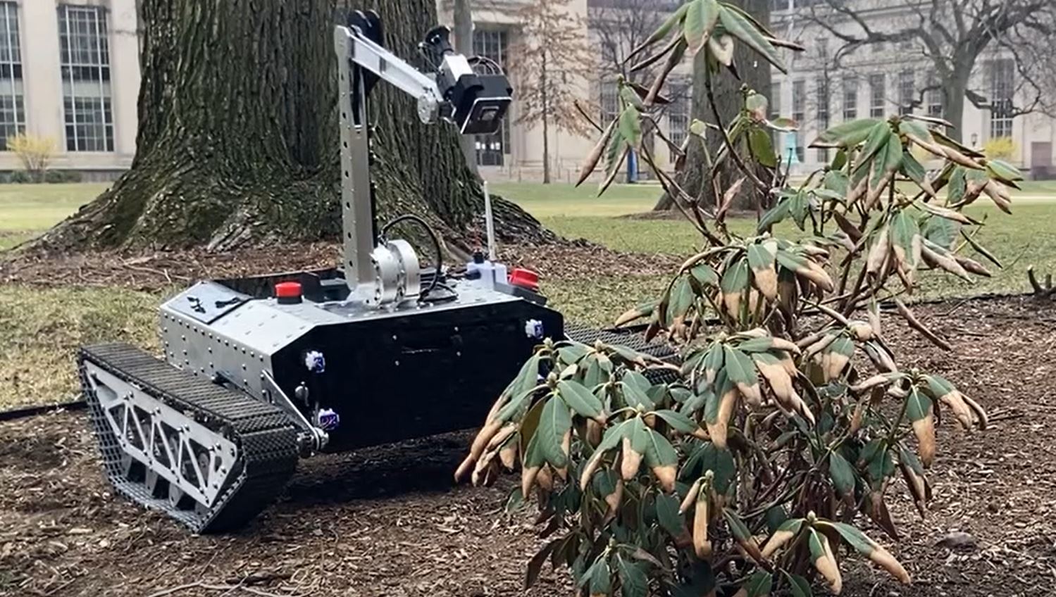
The Agrobot Rover. My Master’s Thesis.
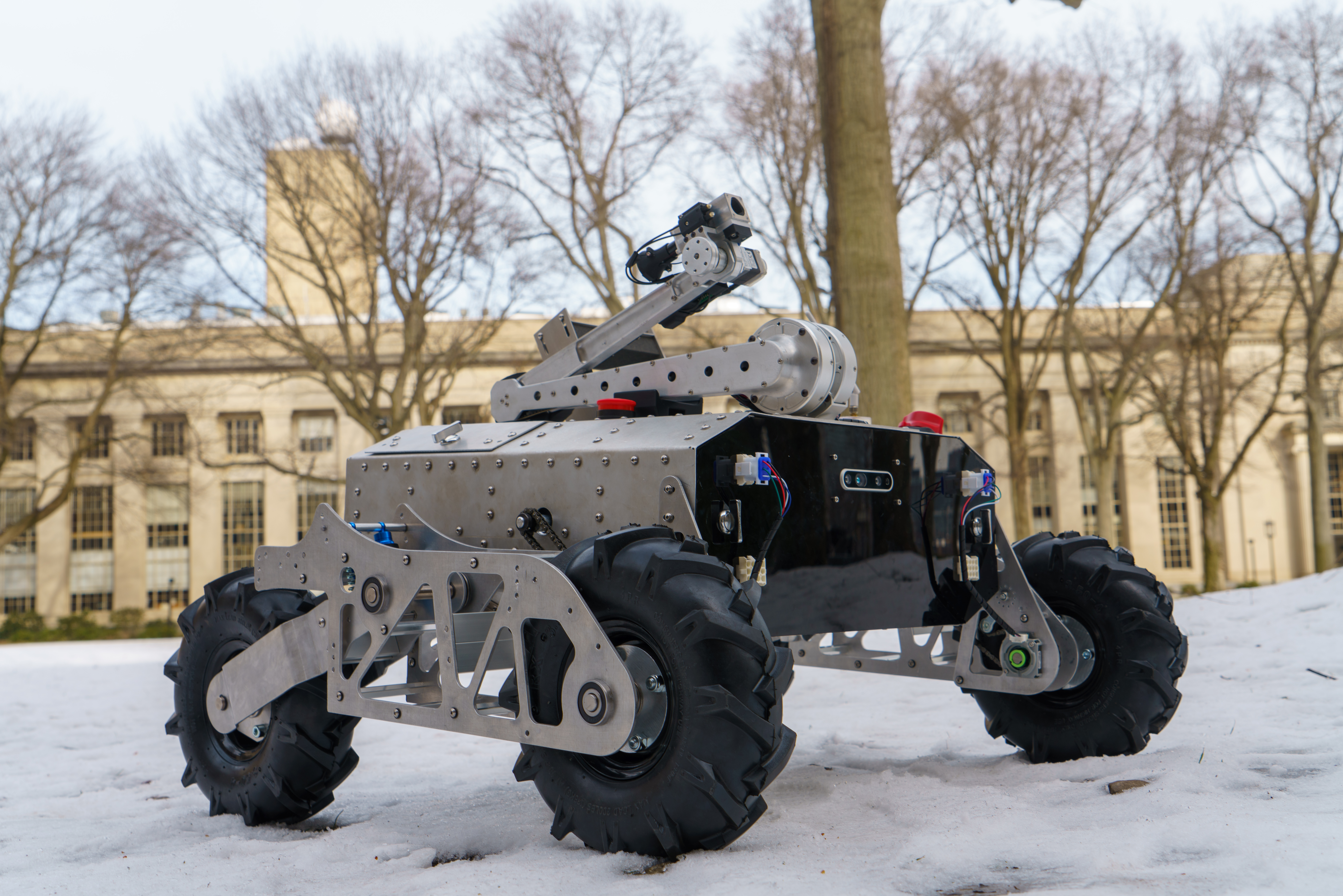
I worked on this robot with another graduate student in the lab, Marc-Andre Begin. He was responsible for the main body of robot. I was responsible for the robotic arm, the miniature tool changer at the end, and a suite of prototype tools. I would later replace the treads of Rover V2 with heavy-duty all terrain wheels in Rover V3.
There is so much material to discuss here. For the full thesis, follow this link here.
Paper on the streamlined PID tuning procedure (accepted to IEEE Robotics and Automation Letters (RA-L) and IROS) is here: Download PDF
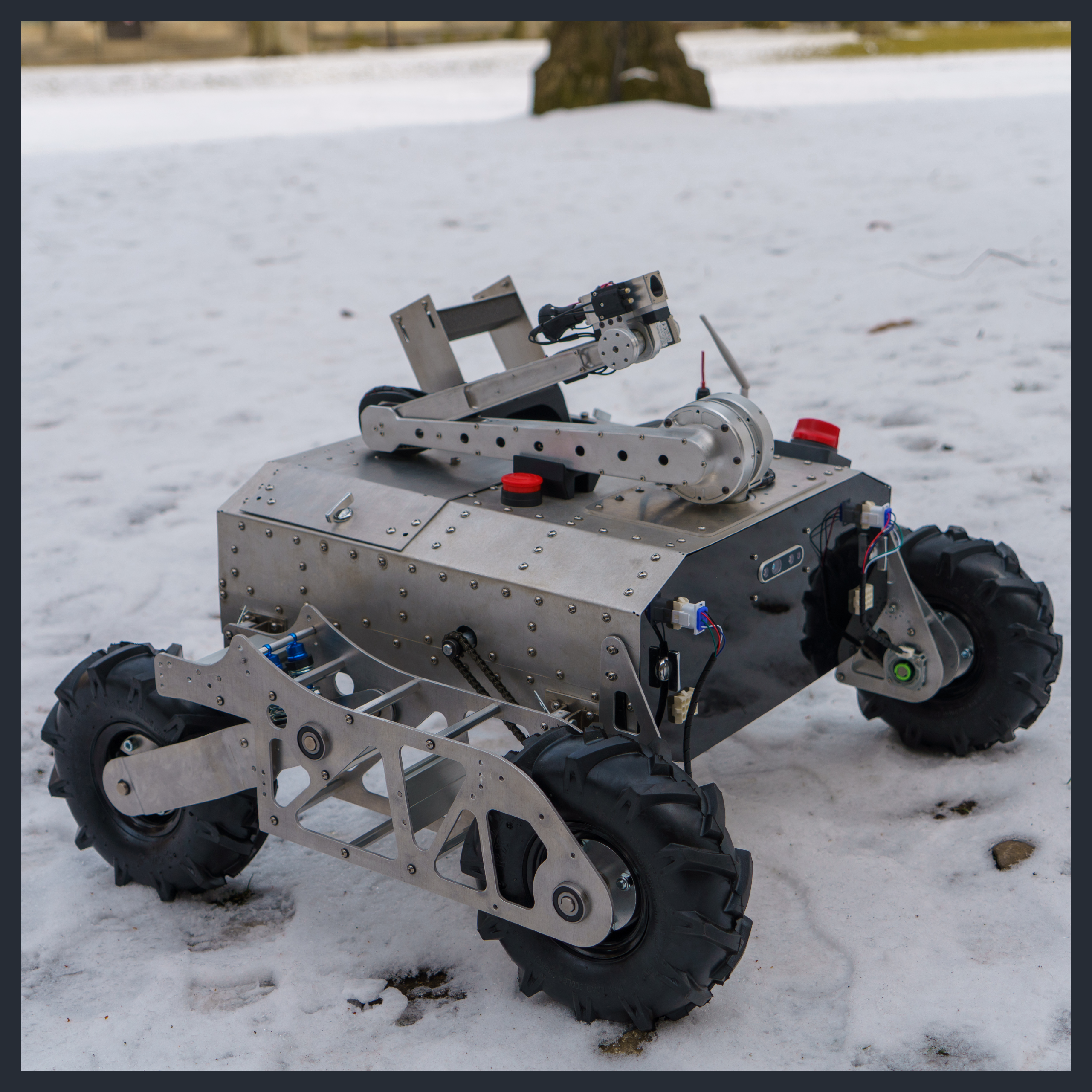
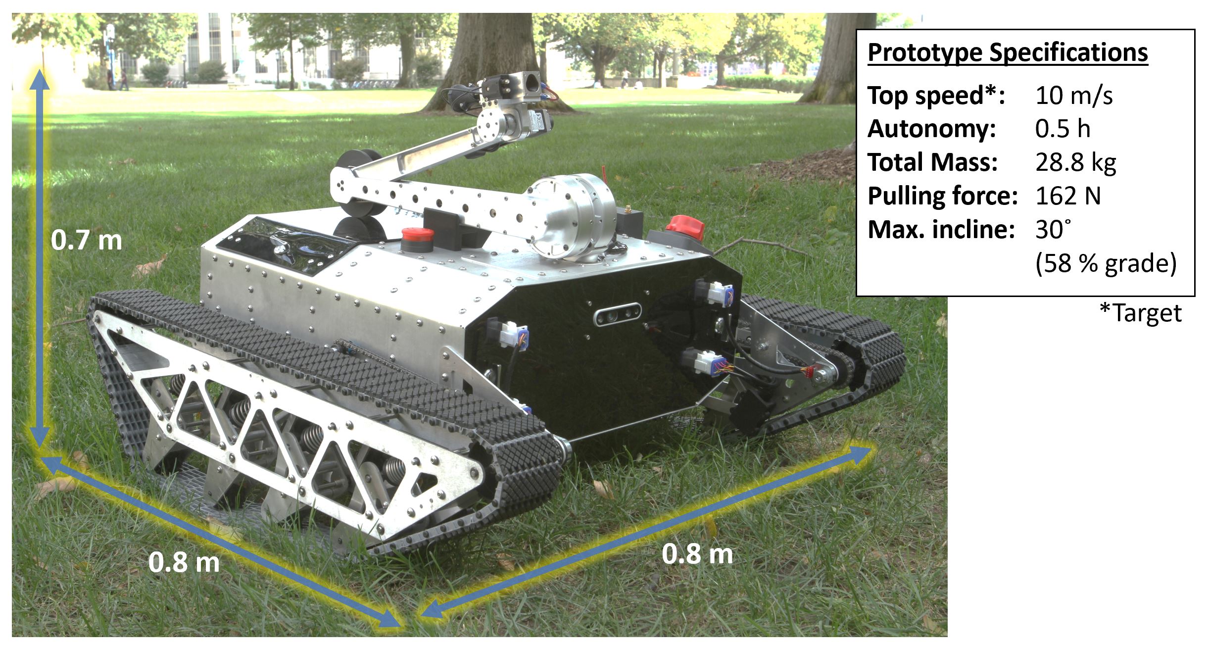
The Rover Overview
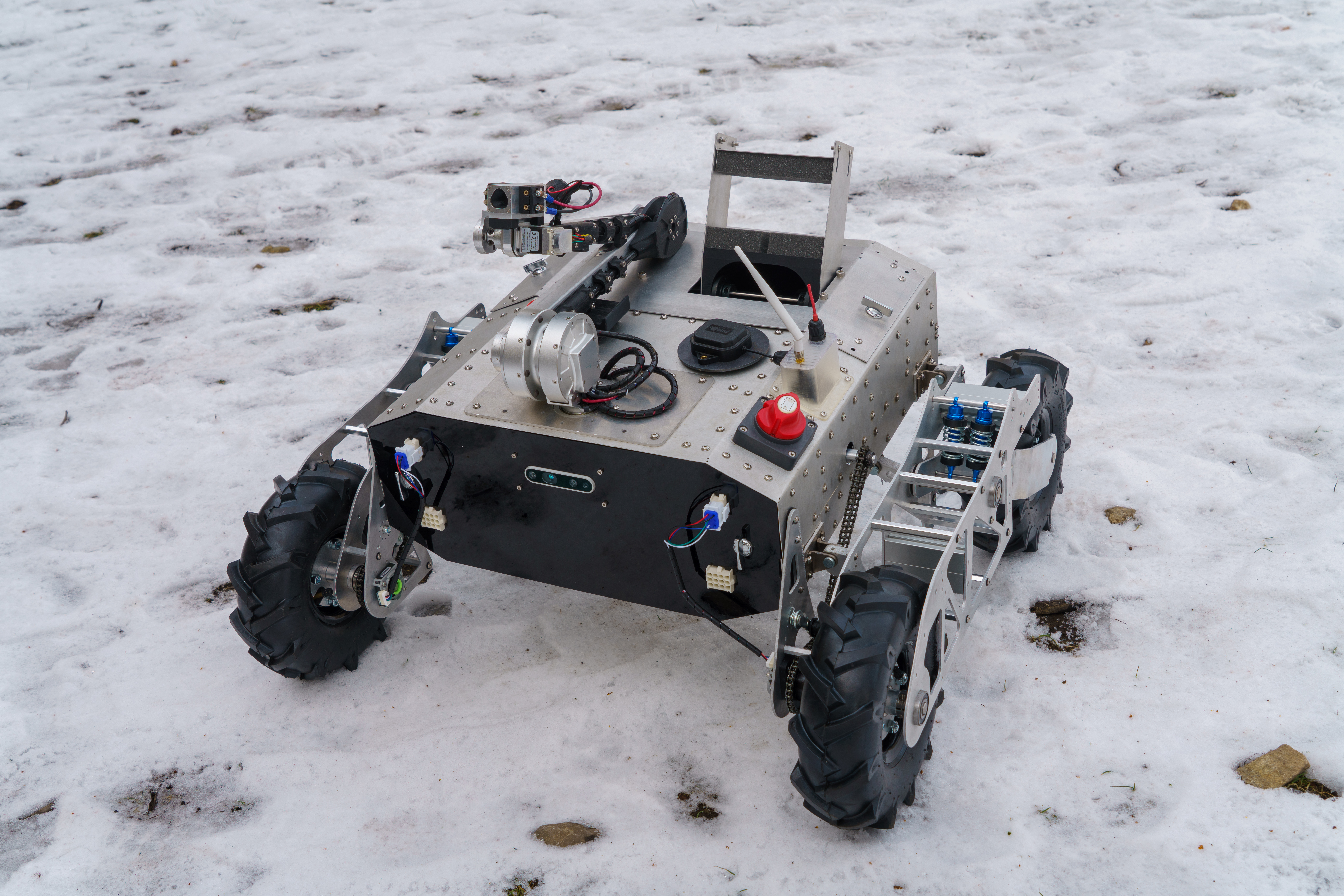
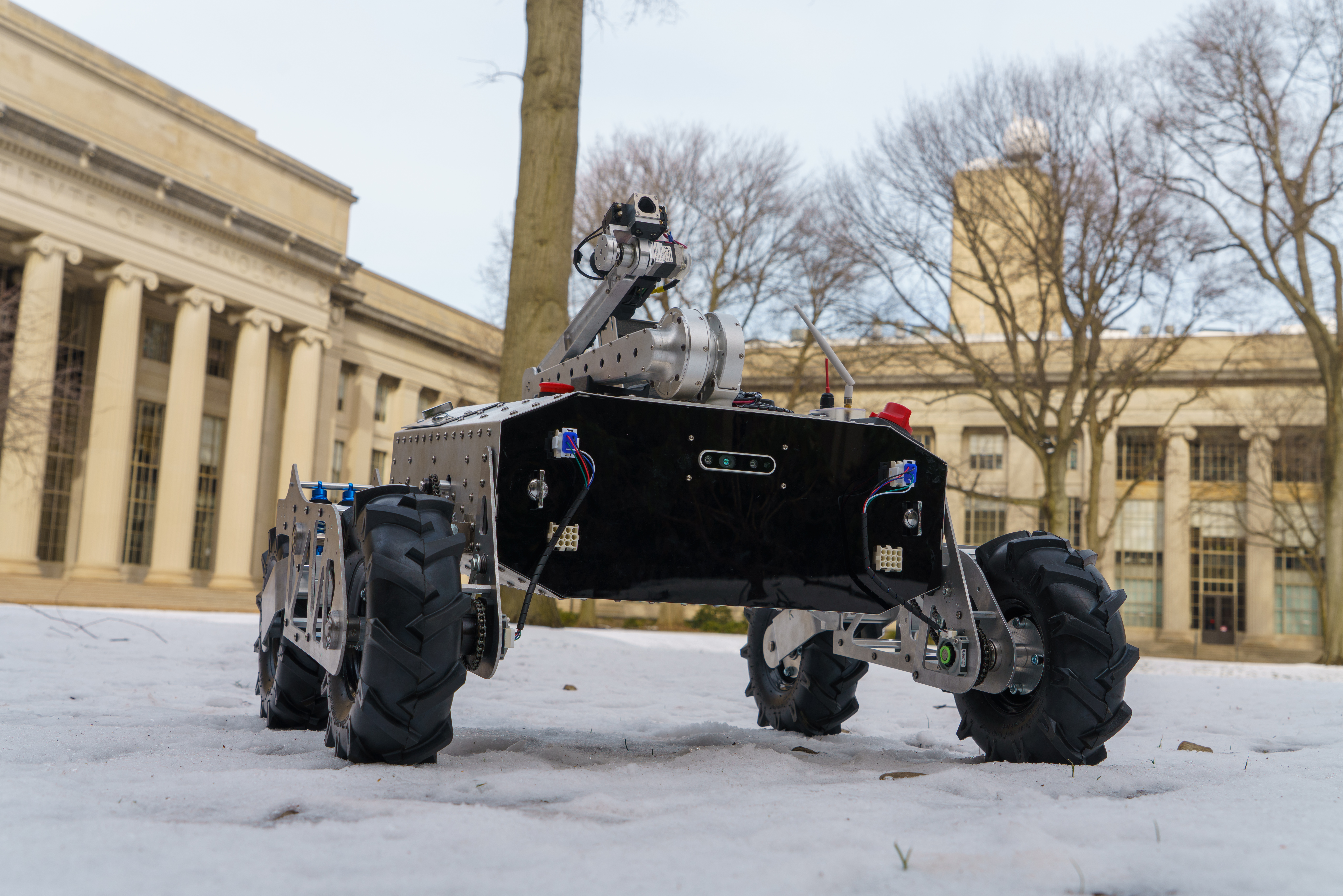
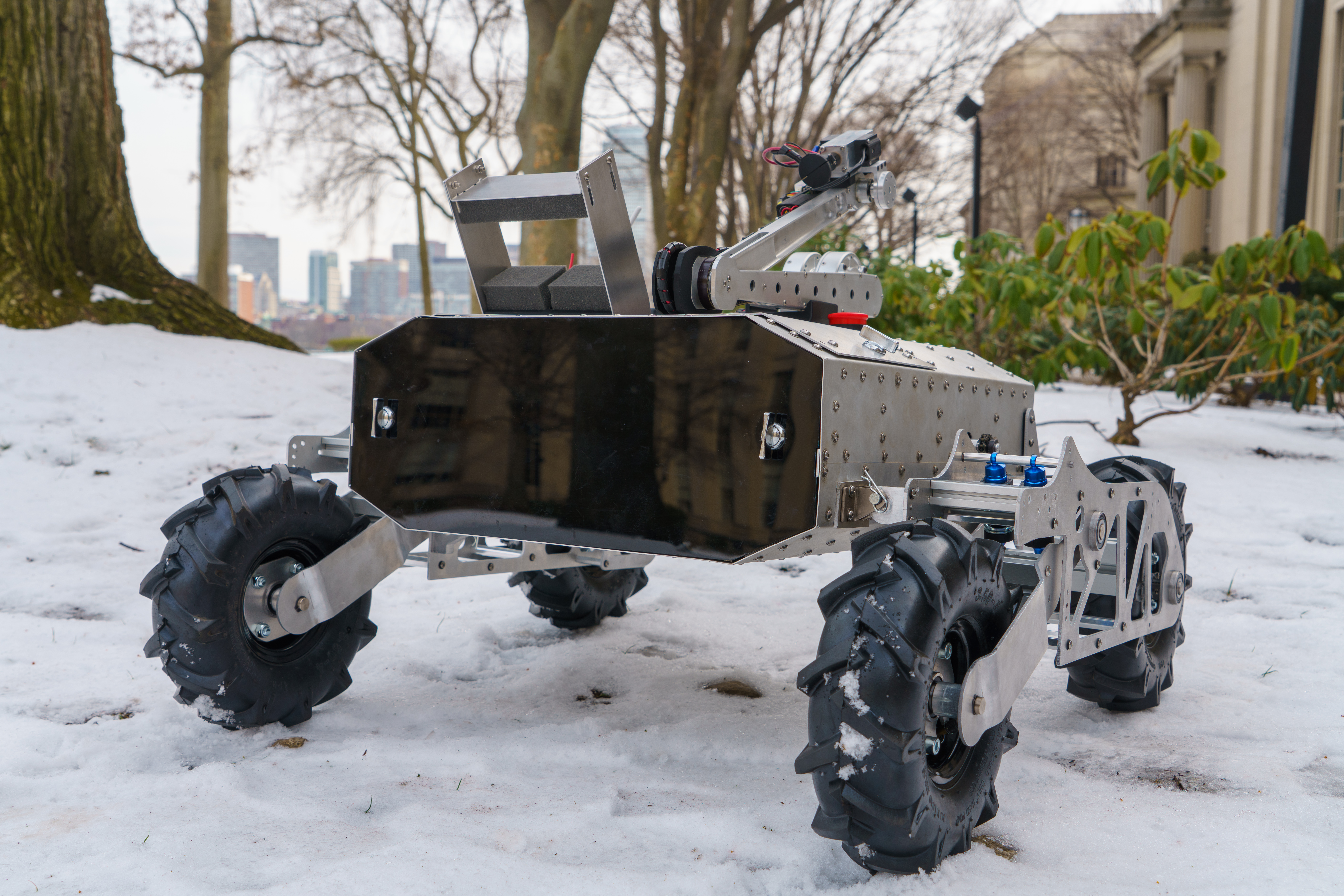
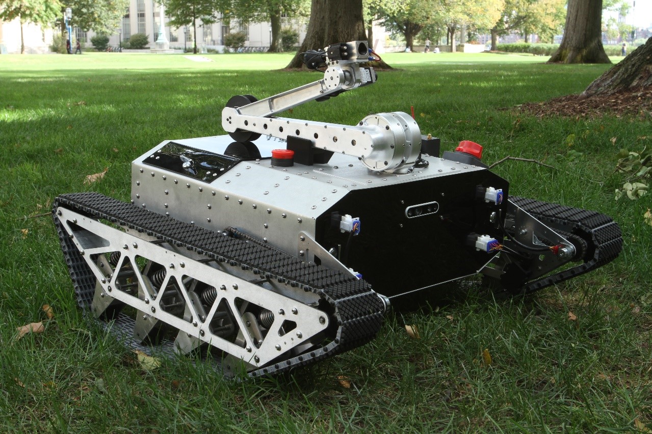
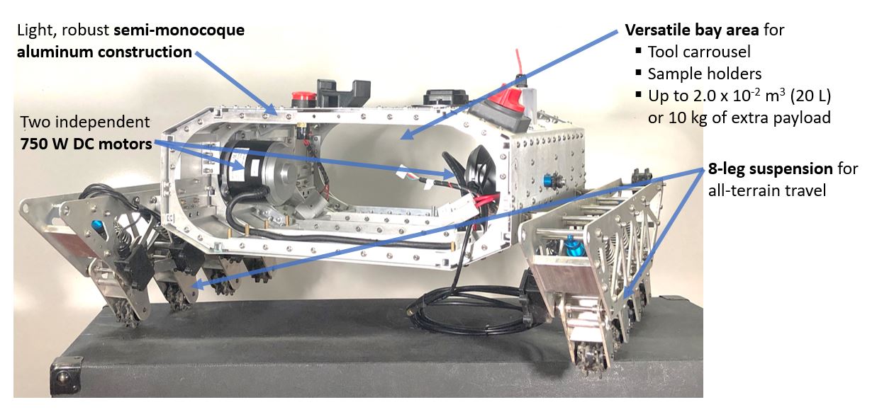
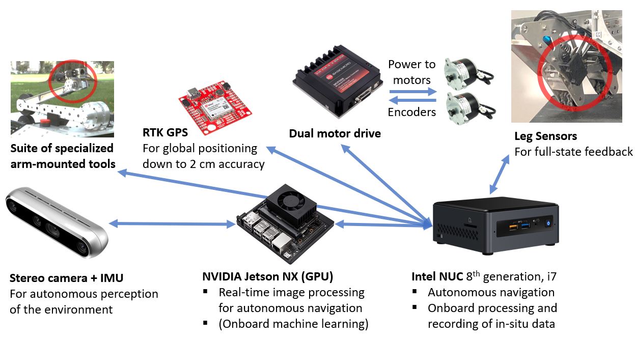
The main body of the Agrobot houses an Intel NUC, GPS, Intel Realsense camera, and massive electric brushed scooter motors. A powerful high current BasicMicro motor controller drives these motors. In the back of the rover is a docking bay that currently holds a battery but can also be used to house larger tools, such as methane cameras or other robots.
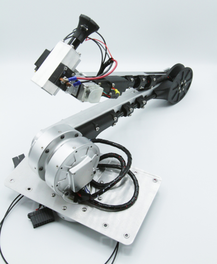
The Arm
The arm has four degrees of freedom and boasts a miniature tool changer mounted on the wrist at the end. Most of the motors are mounted at the base of the arm in order to reduce the inertia at the joints.
Design and Manufacturing
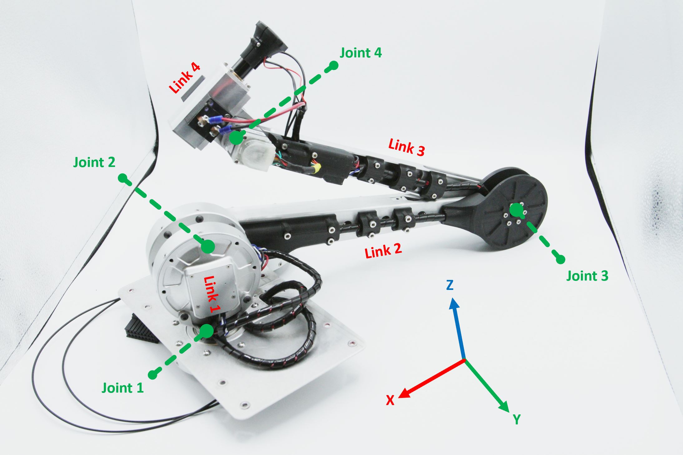
Arm Design
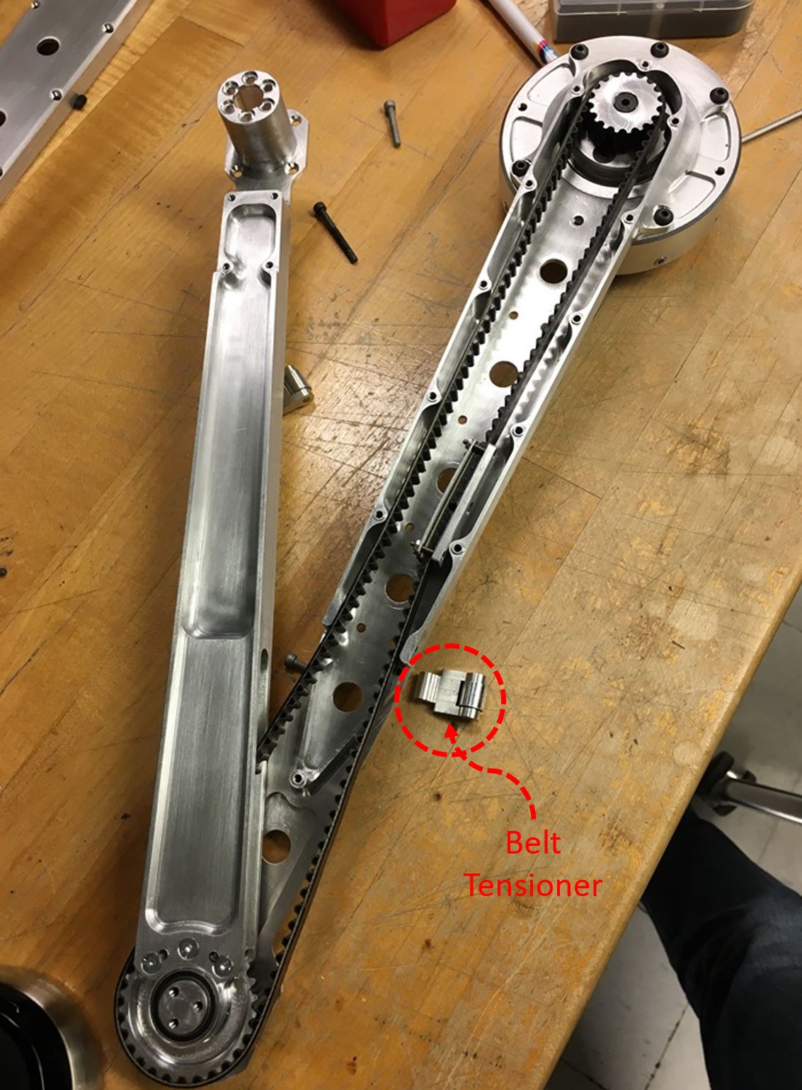
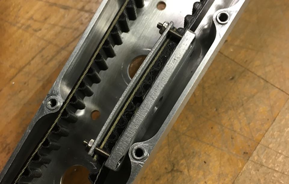
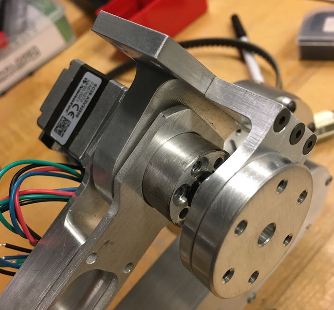
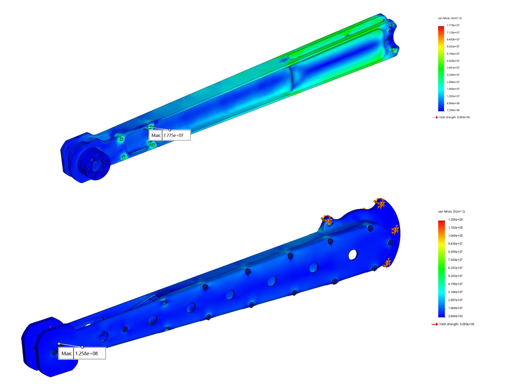
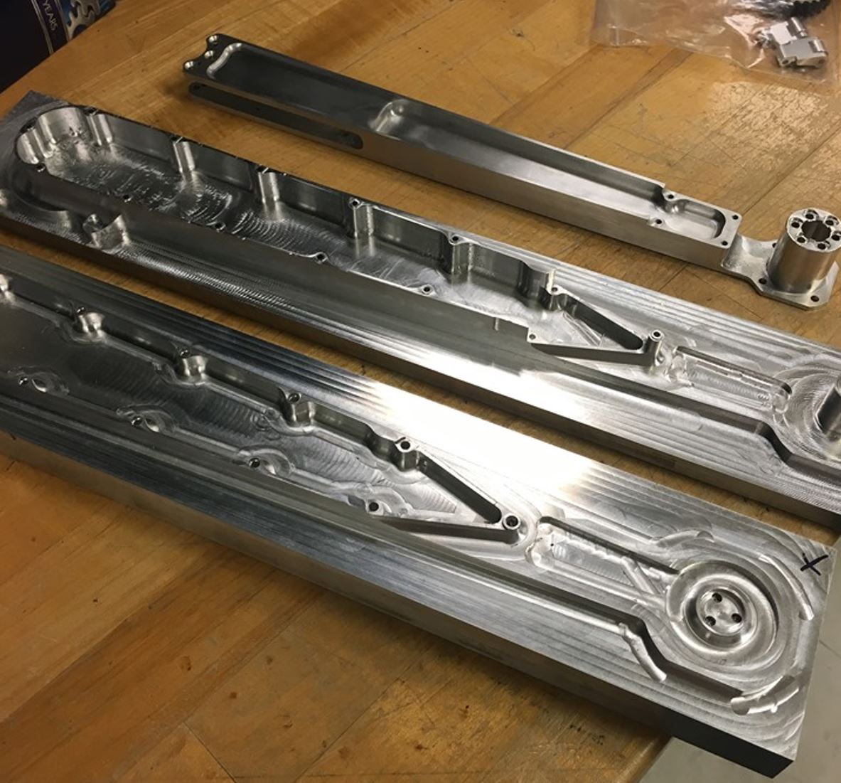
The design of the arm was based on the leg of the Mini Cheetah robot that was built in the MIT Biomimetics Lab. With the motors mounted at the base, less torque is needed to accelerate the links of the arm. The third joint of the arm (rotating about the elbow) is actuated via a belt transmission that is housed in Link 2. For ease of manufacturing, assembly, and installation, the belt was cut and then spliced together, as the belt was expected to have a limited range of motion. At the wrist is a geared stepper motor that actuates the last degree of freedom, and the wrist itself has holes for bolting other attachments besides the tool changer if needed. This entire assembly is made of 7075 aluminum (machined by me on a very old Haas 3-axis CNC) and can withstand all the expected forces, even an unintentional one meter drop test.
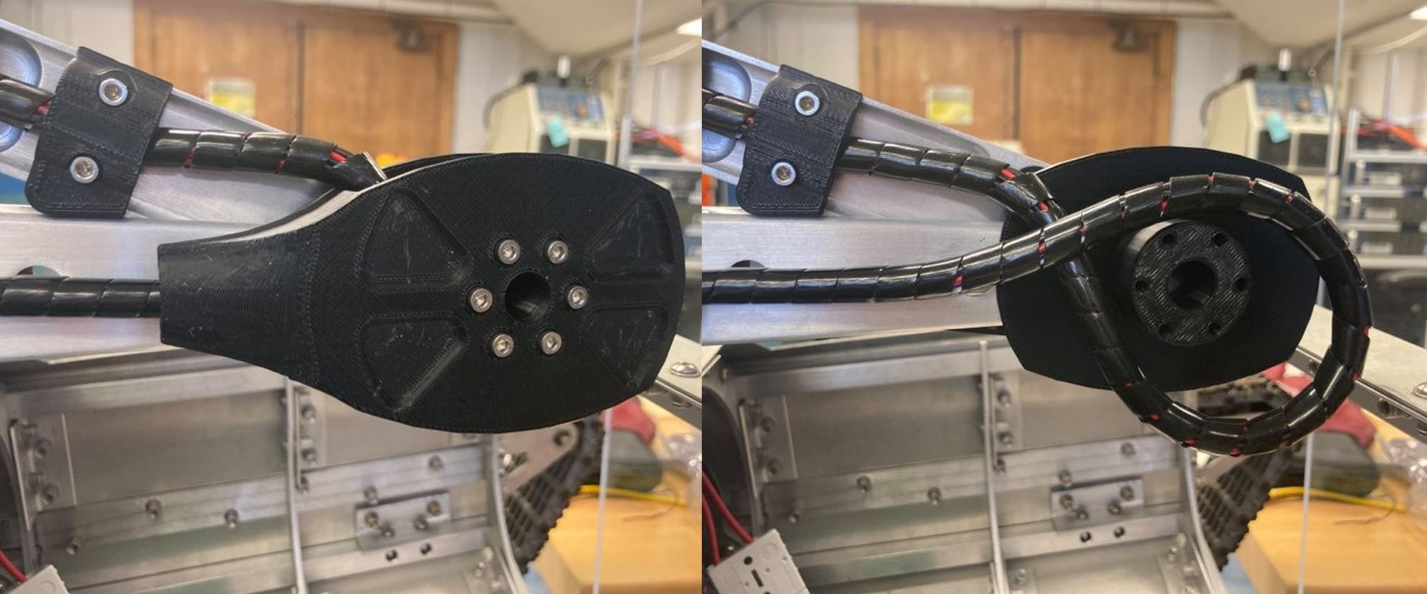
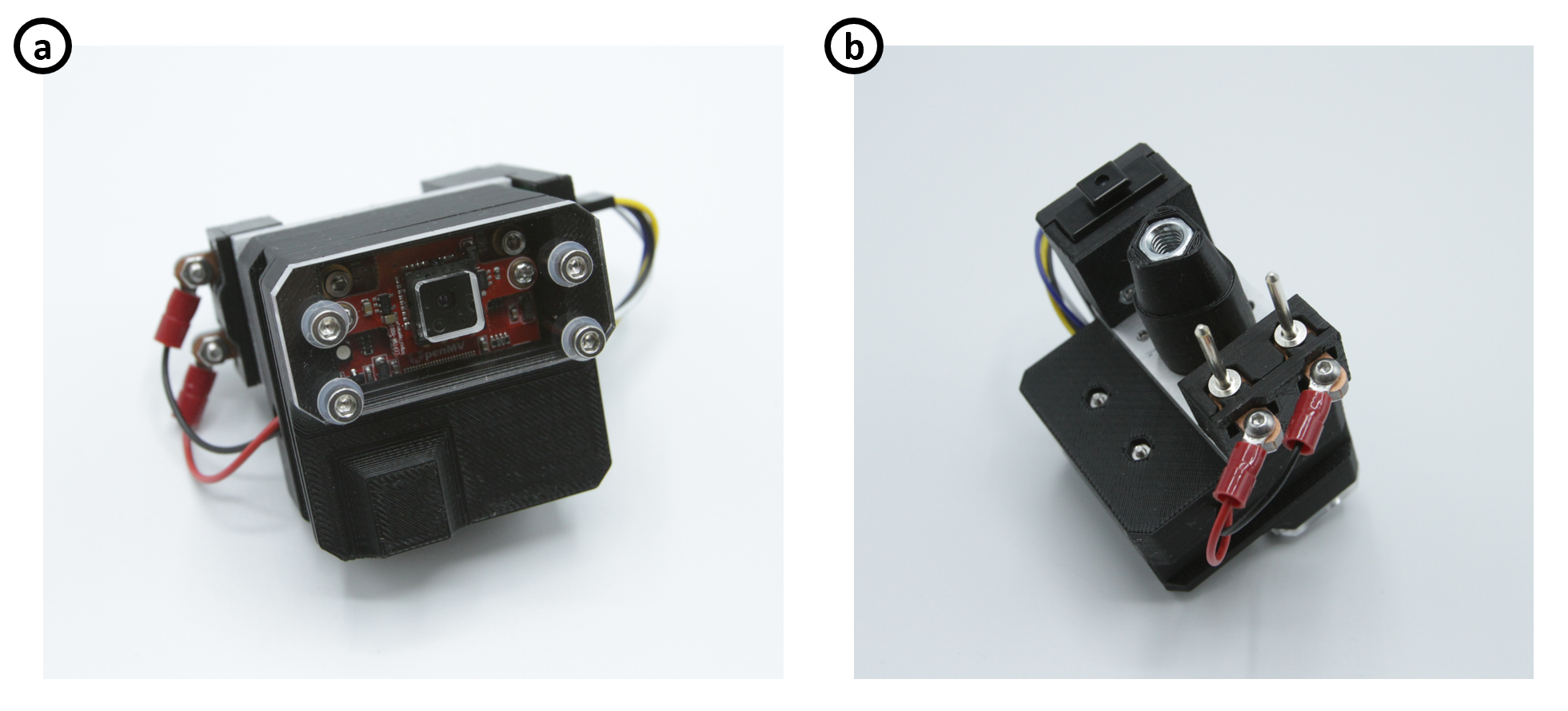
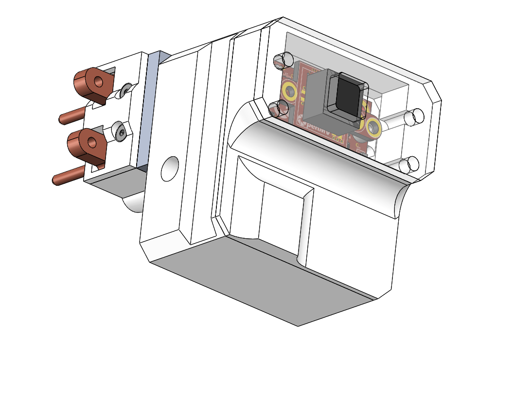
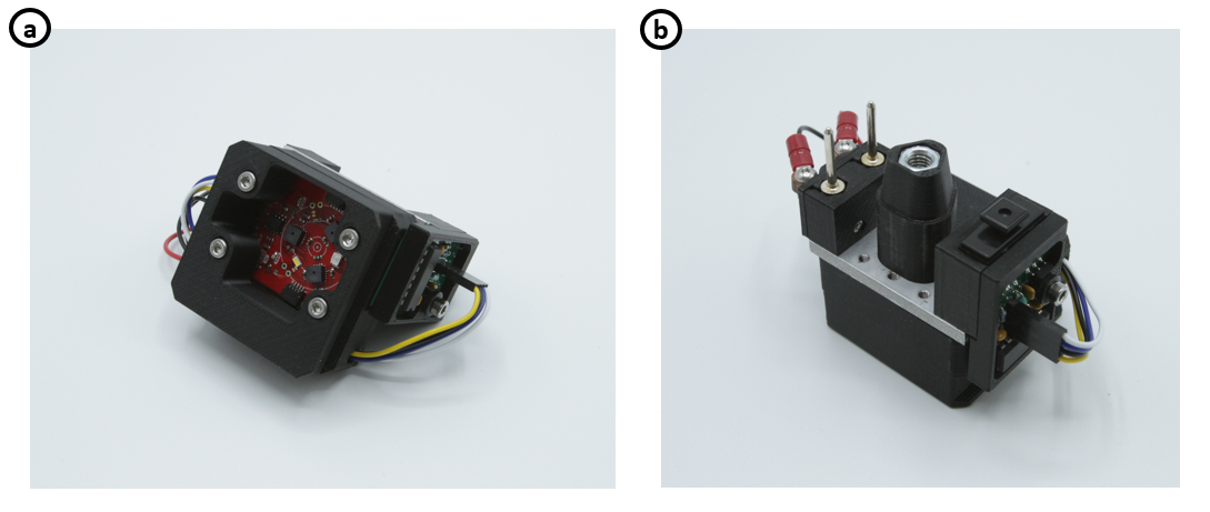
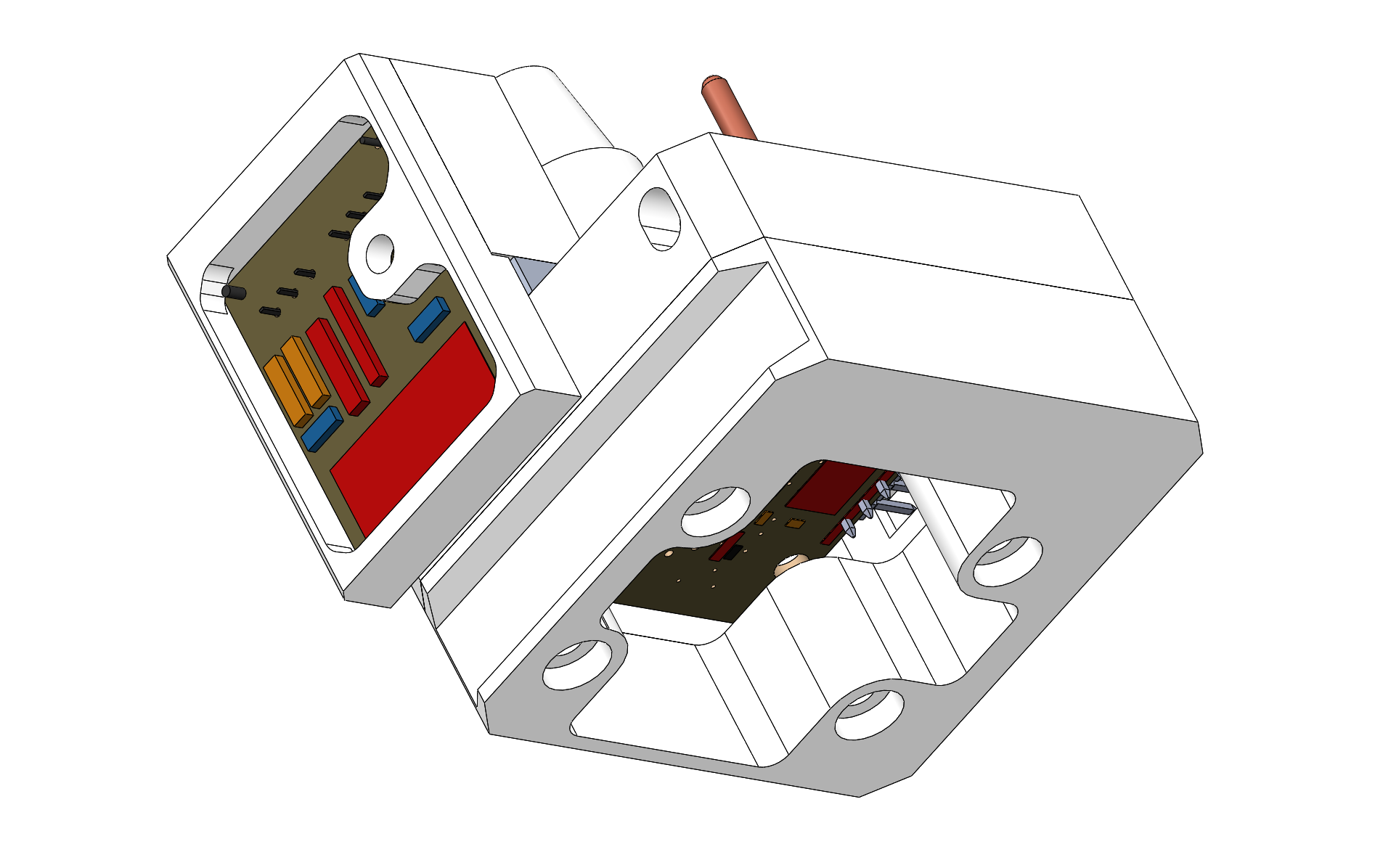
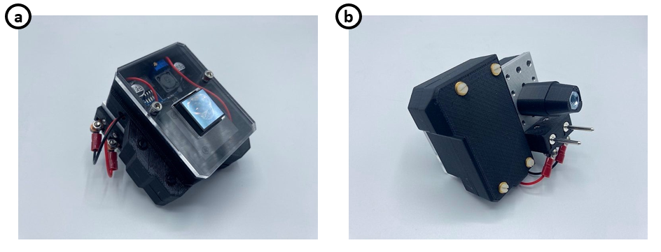
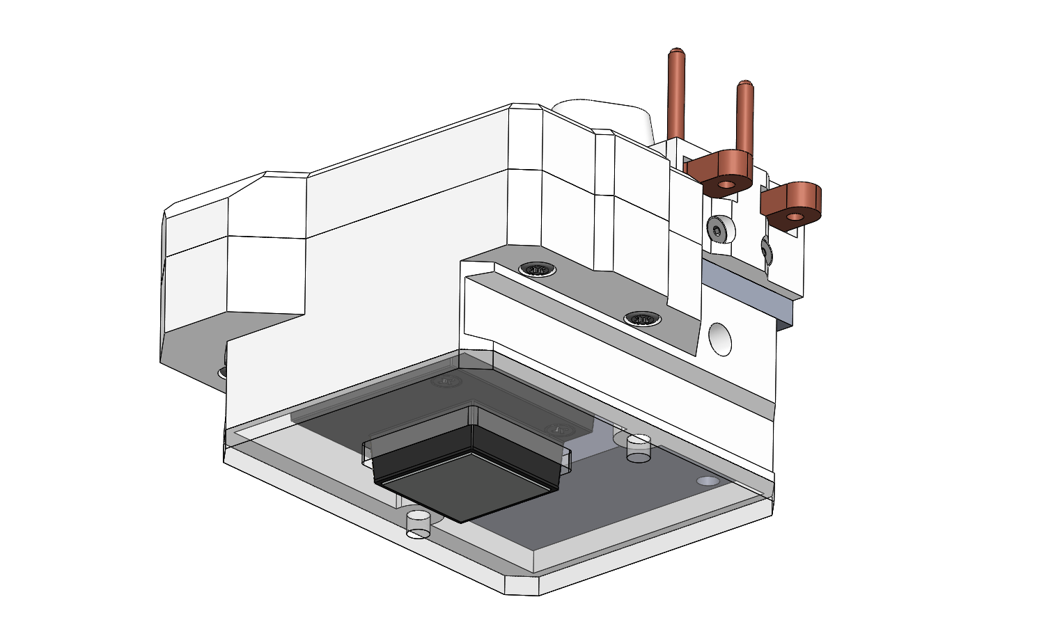
Miniature Modular Tool Exchanger
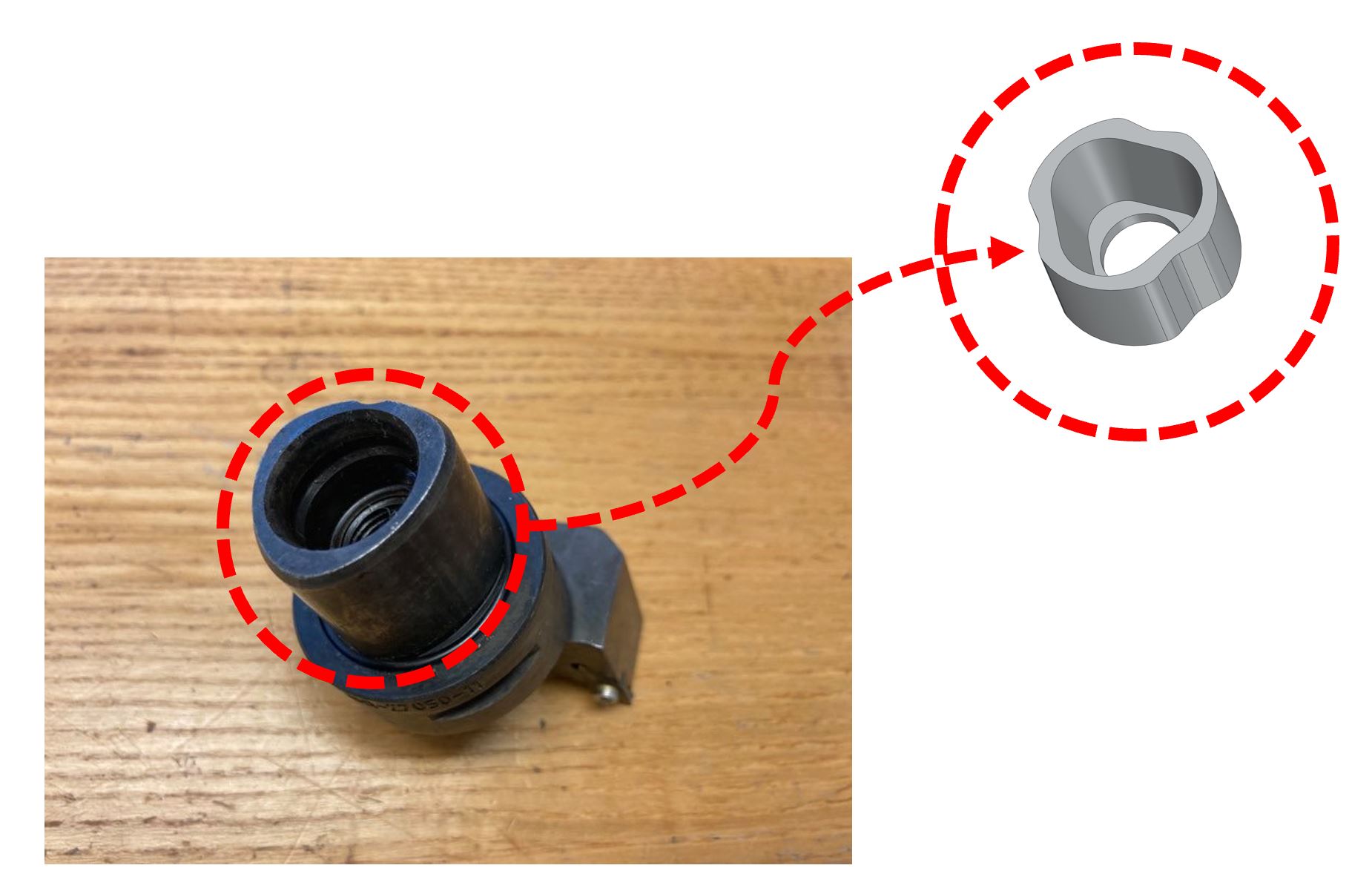
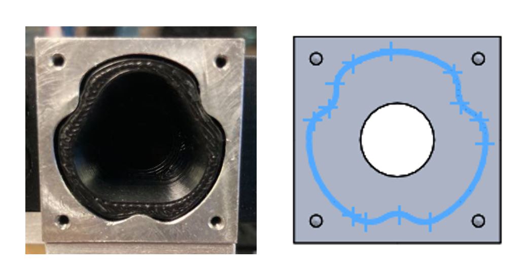
The miniature modular tool changer is mounted onto the wrist of the robotic arm and is designed to take in different types of tools. Inside the tool changer is a triangular lofted socket that matches the corresponding plug on the various tools I built for this project. The socket and plug were designed to be very similar to what I saw on a Mazak turning center that my lab had at the time. Once the plug enters the socket, there is a threaded stud that rotates until the plug is completely drawn in.
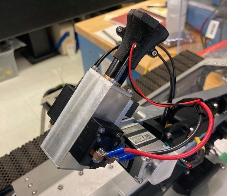
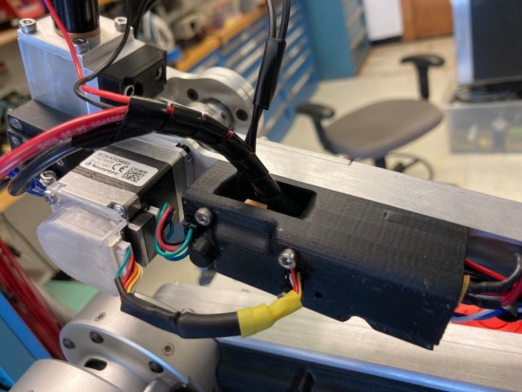
Electronics
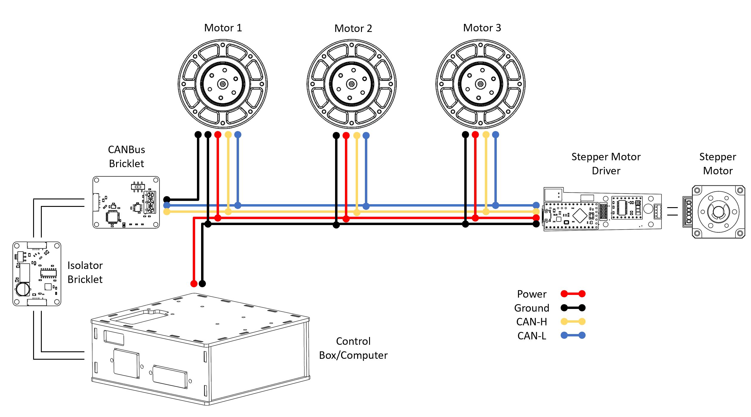
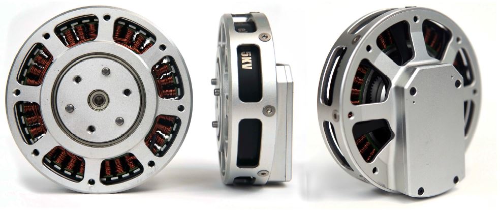
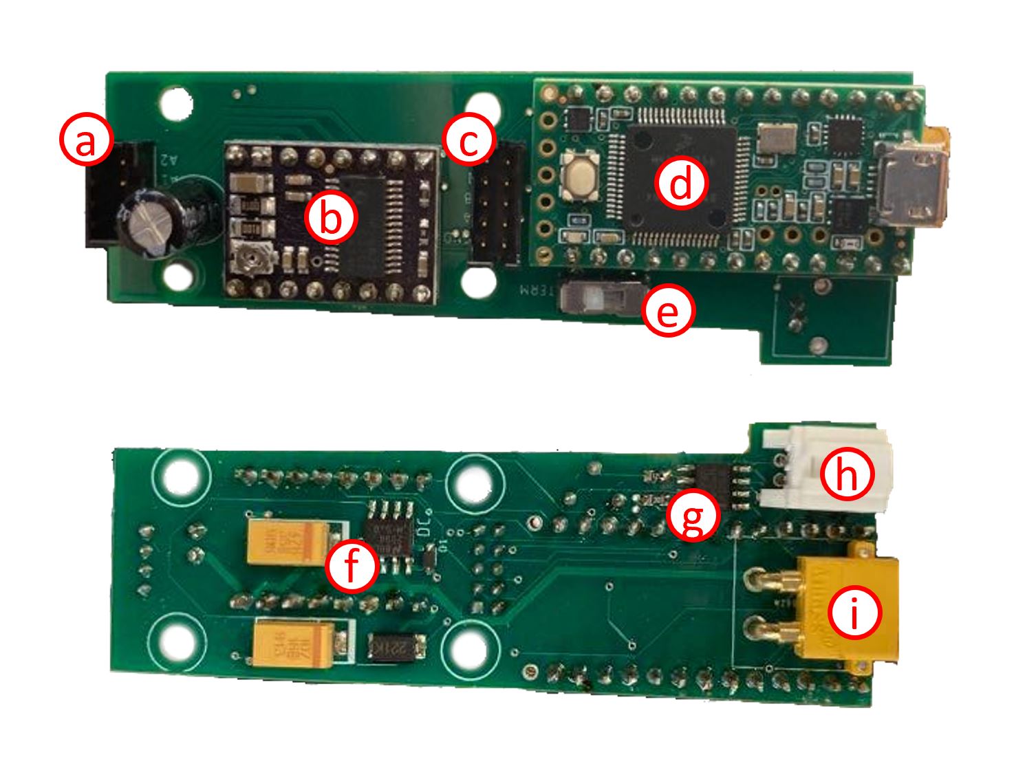
The first three joints on the Agrobot arm are driven by Mini Cheetah motors, which are high torque density brushless motors with a built in motor controller that is CANBus compatible. As mentioned before, the wrist is actuated by a stepper motor. I designed and built a custom PCB with a CANBus transceiver, stepper driver, Teensy, and step-down buck converter that can be placed on the CANBus daisy chain. The wires travel the length of the arm and connect to the arm control box. The box has a bunch of Tinkerforge bricks and bricklets acting as CANBus transceivers and safety switches.
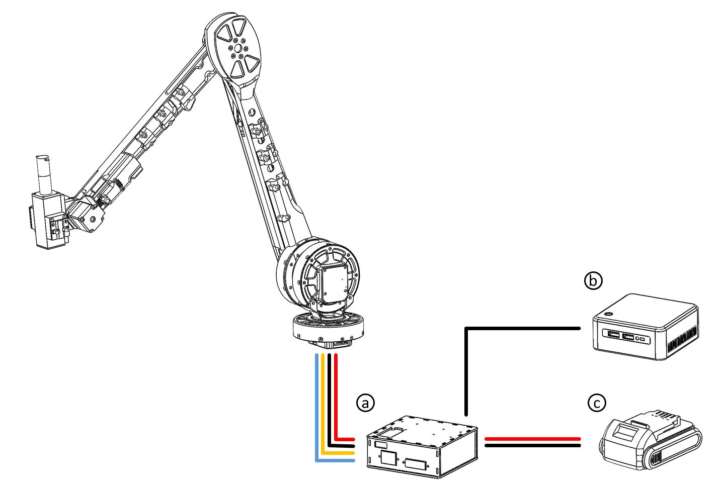
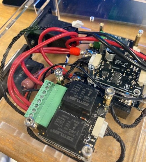
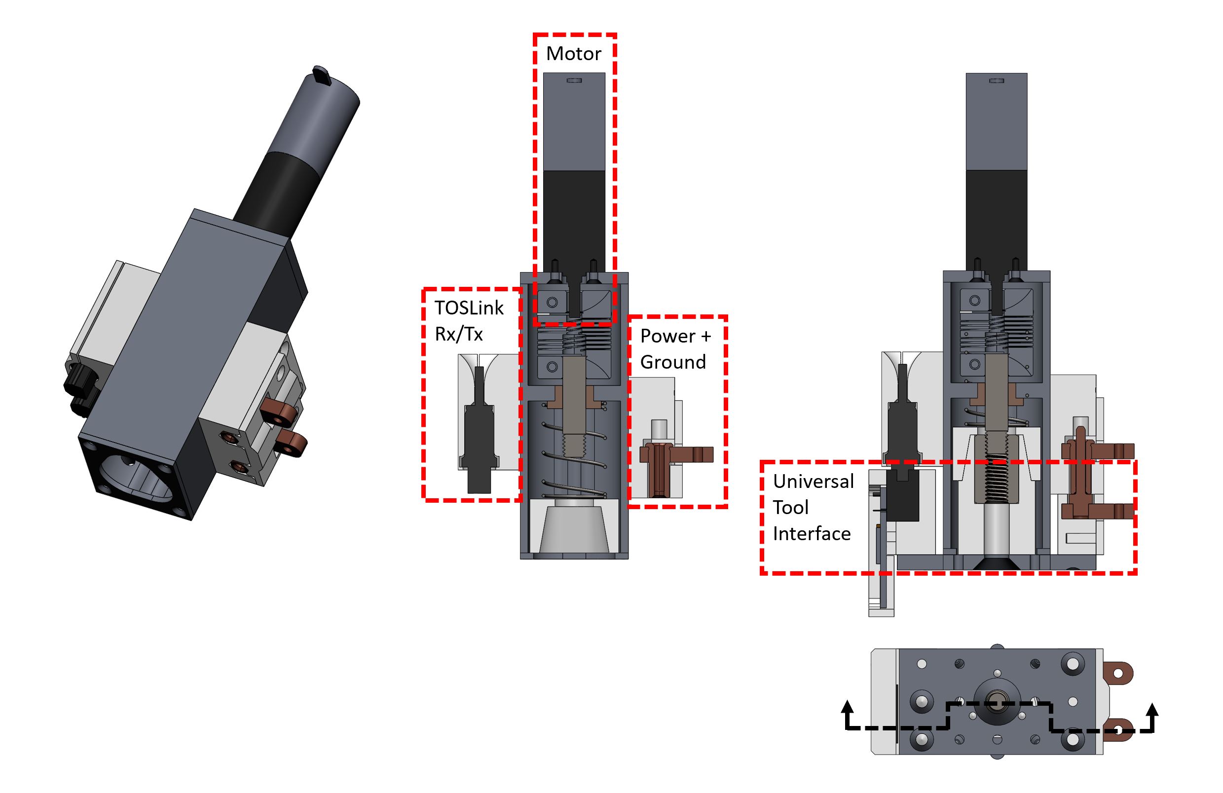
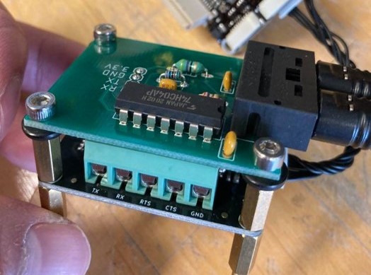
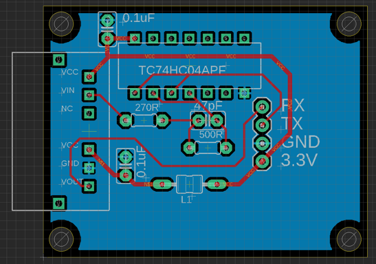
The control box contains several hardware parts for operating the tool changer. First, there is a Tinkerforge DC brick to drive the brushed motor on the tool changer. On the tool changer, there are two ports: one delivers power/ground and the other receives and sends data over a TOSLink optic cable. Hence, in the control box, there is a custom PCB I made that fits in the Tinkerforge infrastructure. It uses the TTL pins on the RS232 bricklet to send and receive data over a TOSLink transceiver. There is a Tinkerforge relay that turns on and off the power for the tool. The power and ground sockets/pins on the tool changer itself are low force insertion sockets and pins from Methode Electronics.
Programming Infrastructure
I wrote a ROS package to control the arm and the tools. There are two ways to control the arm. One is an automated method, where you can run a pre-planned trajectory for the arm joints. To generate this trajectory, one option is to send a stream of joint commands. Another option is to physically move the arm to the desired positions and then save those joint positions, similar to Universal Robot collaborative arms can be programmed. The second method of controlling the arm is manually, where you can move the joints incrementally using keyboard commands. A Github repository for all of this can be found here.
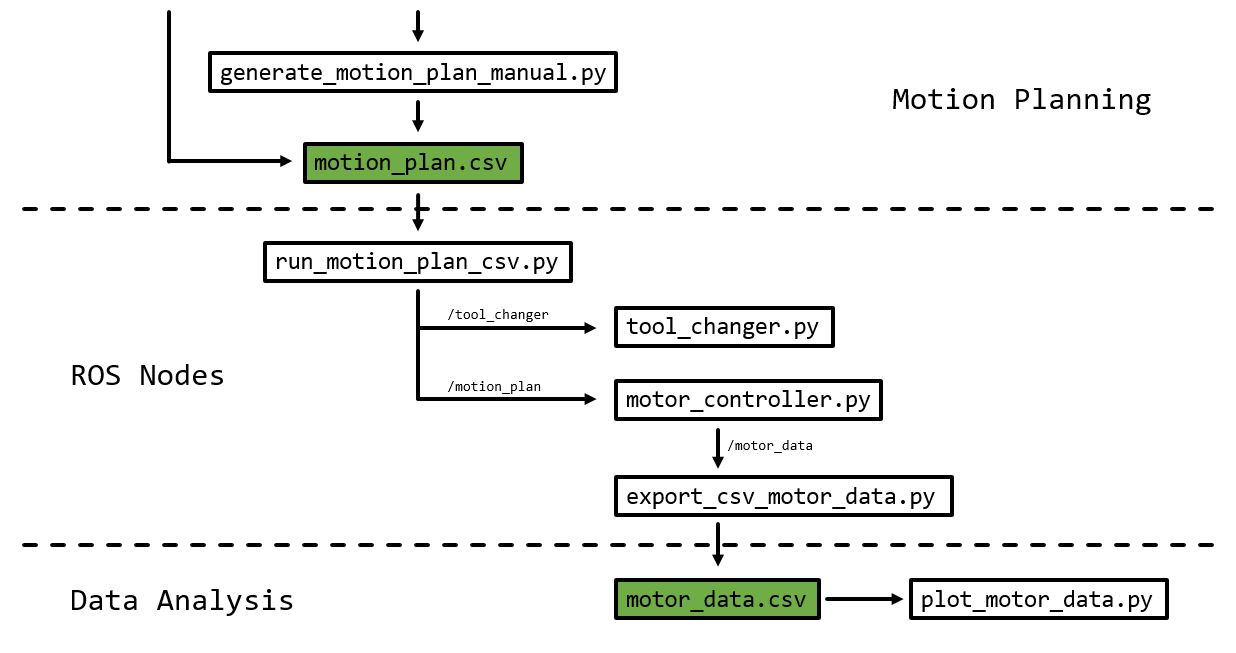
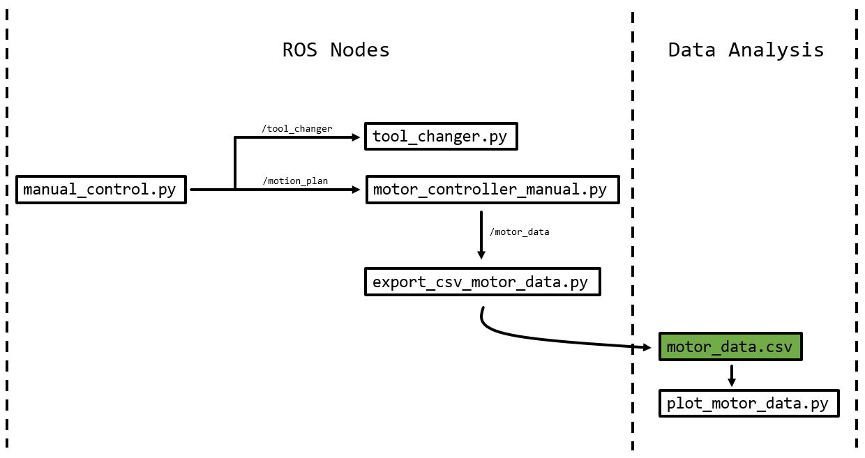
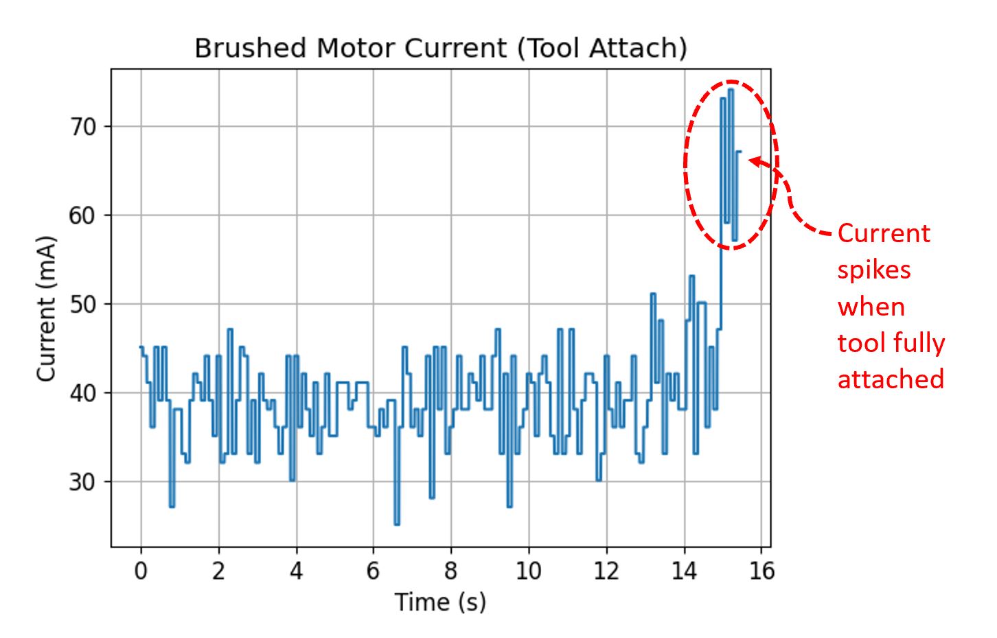
As for running the tool changer, the operation is quite simple. The current spikes when plug of the tool is drawn into socket, triggering the brushed motor coupled to the stud to stop immediately. By then, the power/ground pins and the TOSLink interface should have completely meshed, so communication with the attached tool can begin.
Tools and Instruments
These are just some of the tools I built. Honestly, there are so many more tools that can be made for analyzing things not just in agriculture but also in general field work as well. I only built these five as a proof of concept for measuring potentially useful metrics on a farm. However, the potential for expanding this side of the project is limitless. Each tool came with a physical interface that is compatible with my tool changer as well as a custom-made TOSLink transceiver board that either communicated directly with the tool breakout board itself or an intermediary microcontroller.
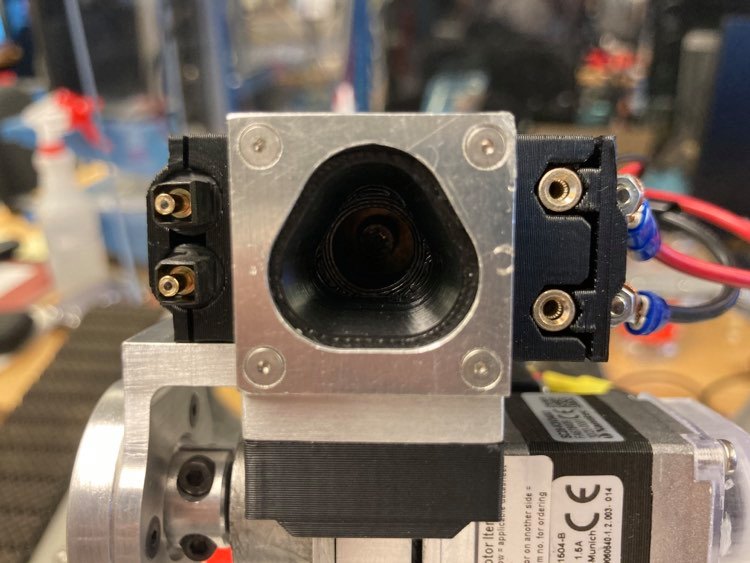
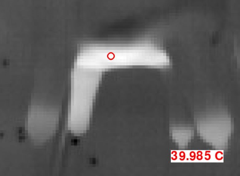
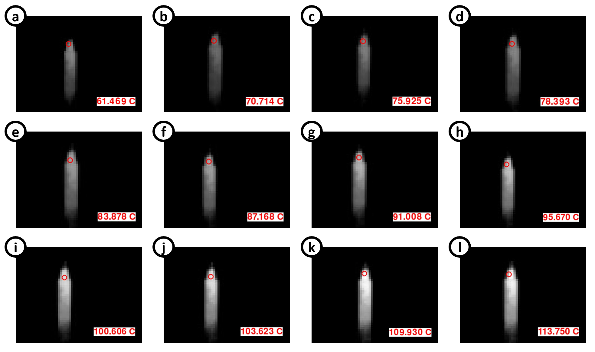
Thermal Camera
The thermal camera is what it sounds like: a thermal camera. It uses an off-the-shelf Sparkfun breakout board with a FLIR Lepton camera and MicroPython capabilities. I programmed it to take both pictures and provide live video feed. On the farm, this tool can be used to detect some diseases in livestock that cause perceptible changes in surface temperature.
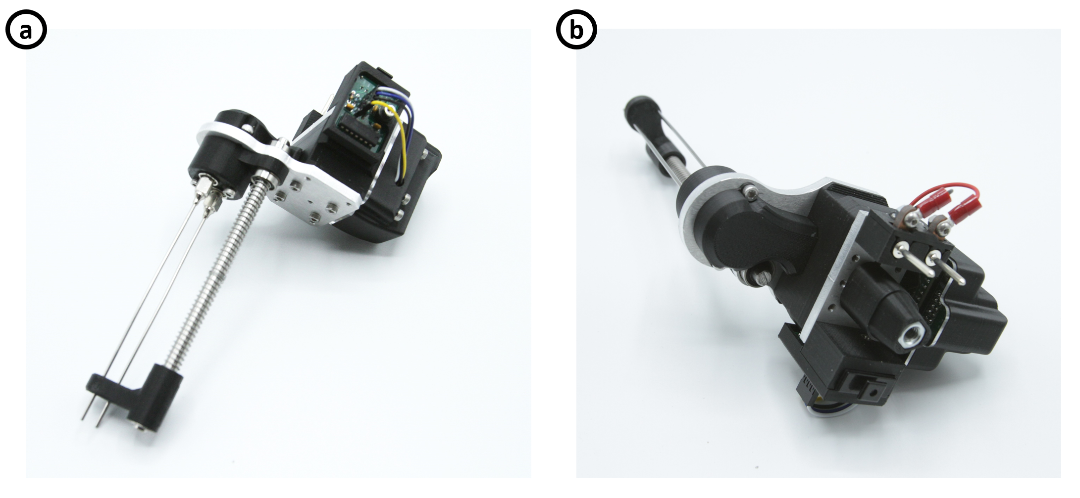
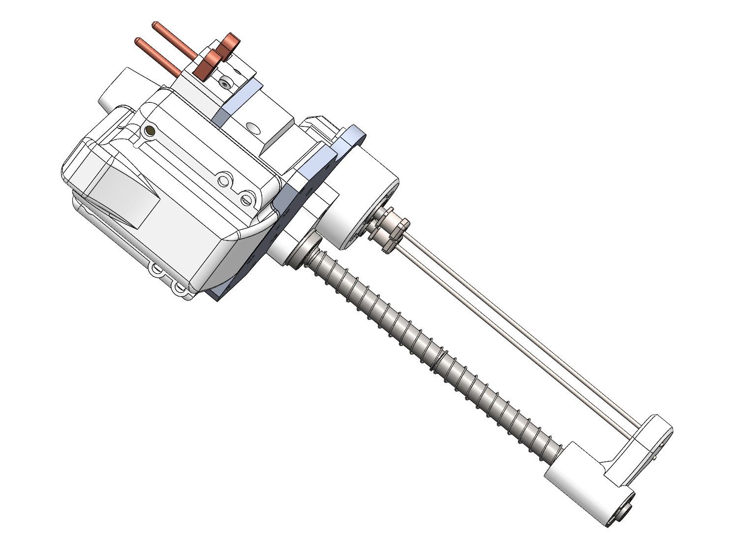
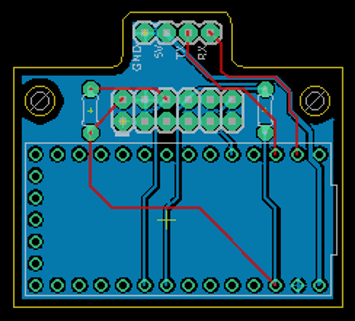
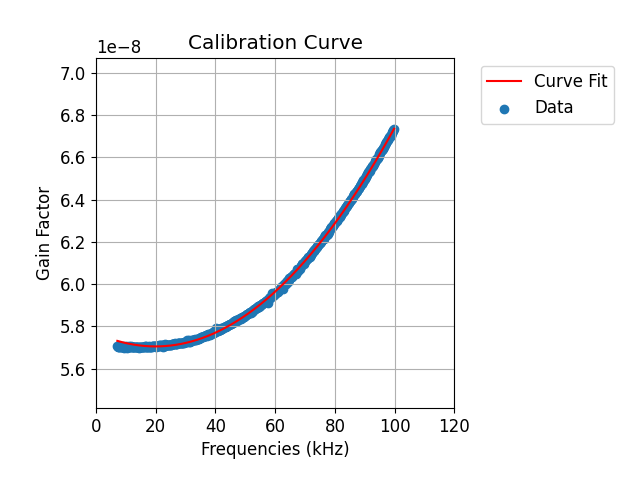
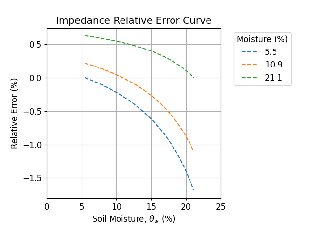
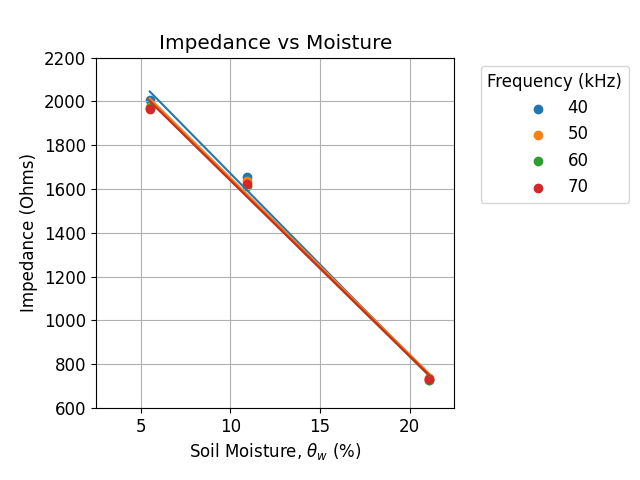
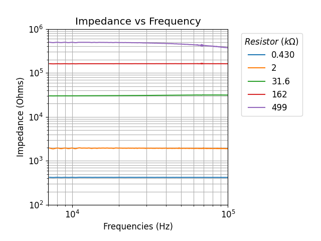
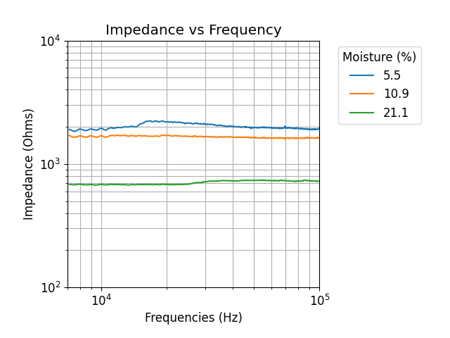
Impedance Analyzer
The impedance analyzer is used to measure soil moisture by doing a impedance measurements over a wide frequency sweep across two probes. These two stainless steel probes are connected to a Digilent pMod-IA breakout board that does the measurements. A Teensy LC and a custom-made intermediary board allows communication between the TOSlink transceiver and the pMod-IA board. The analyzer also comes with a spring loaded “wiper” to wipe off the dirt passively after every use.
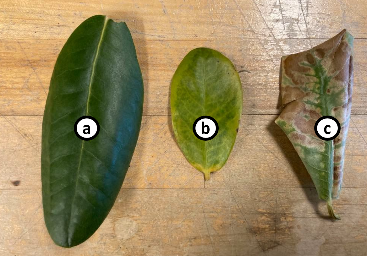
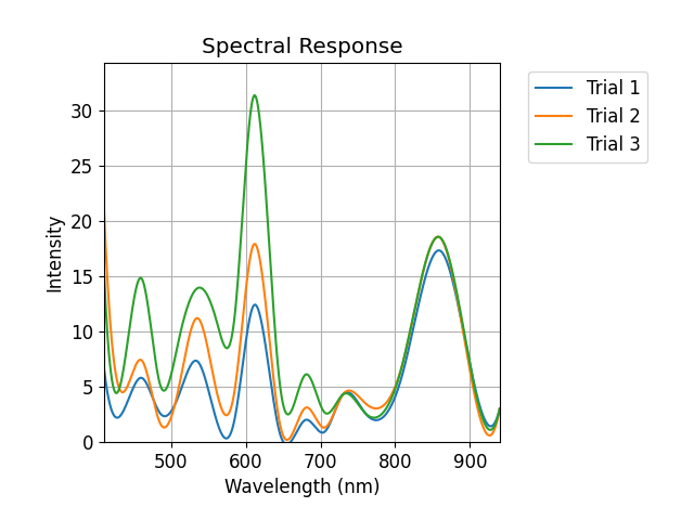
Broad Spectrum Spectroscopy Sensor
This tool uses an affordable off-the-shelf spectroscopy sensor directly connected to my custom-made TOSLink transceiver board. It’s quite simple: light of nine different wavelengths ranging from UV to infrared is delivered to a specimen, and the spectral response is collected. This can be used to determine plant health via differences in color. However, more elaborate calibration (i.e. a better way of quantifying “plant health” and its relationship to the spectral response) might be needed in the future.
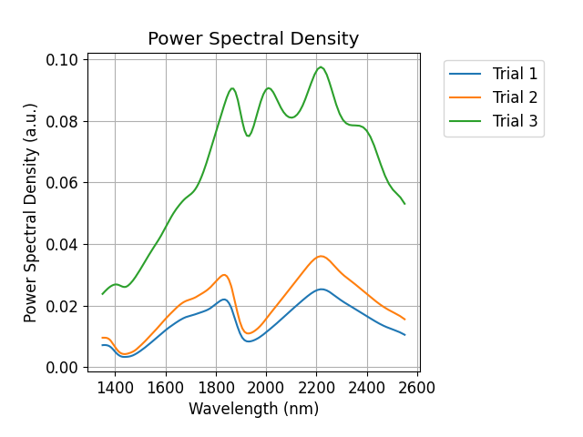
NIR Spectroscopy Sensor
Our lab got a request to use their high resolution NIR spectroscopy sensor for the same purposes (to measure plant health). This device is a lot more expense and has a much higher resolution of wavelengths, but the development package it comes mounted on is physically larger than the other spectroscopy sensor tool. The NIR spectroscopy sensor is mounted to a Raspberry PI Zero and can only be communicated with via Java. It would have been a hassle to integrate the TOSLink transceiver with the Raspberry Pi Zero. Instead, I connected to it via Wifi and had the data printed onto a serial terminal which I could copy and plot on the home Intel NUC computer. It wasn’t the best workaround, but I’ll admit…working with someone else’s Java code is not my forte.
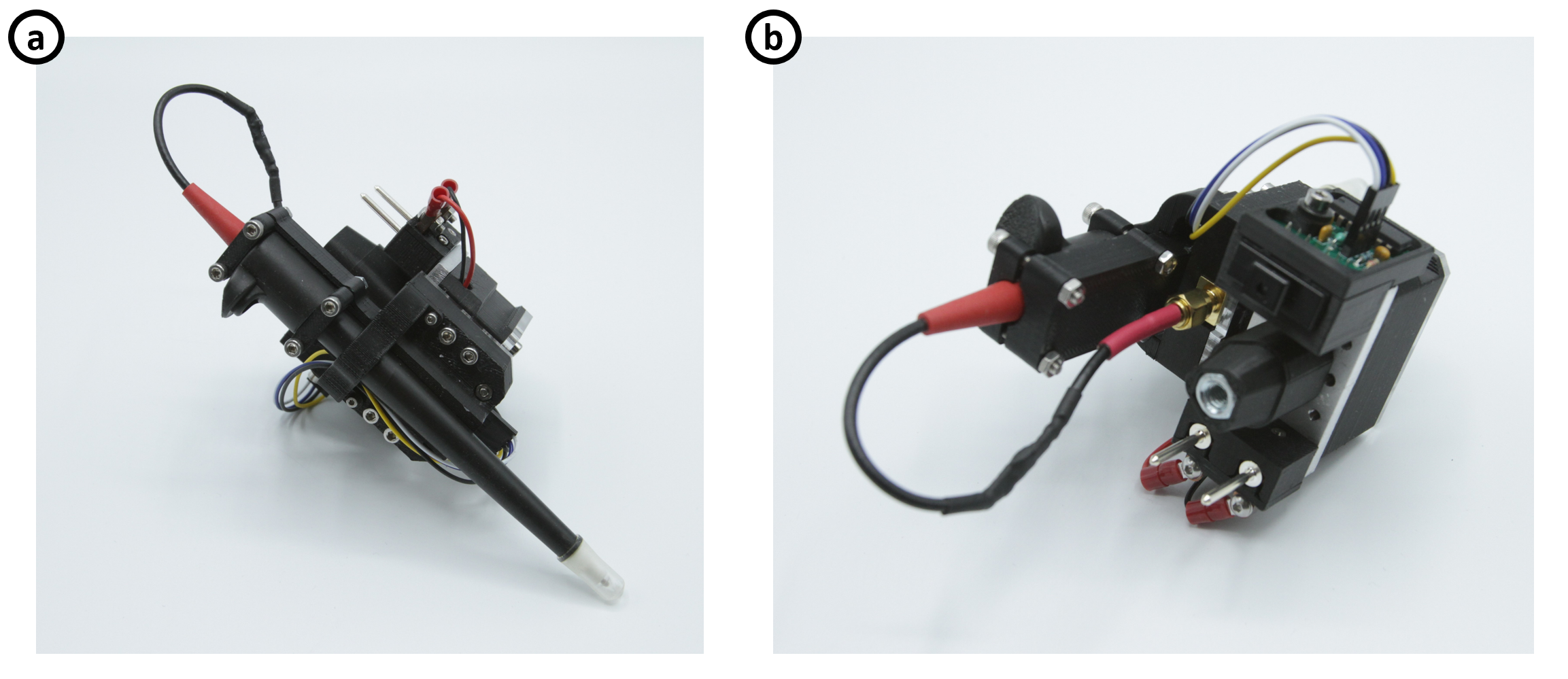
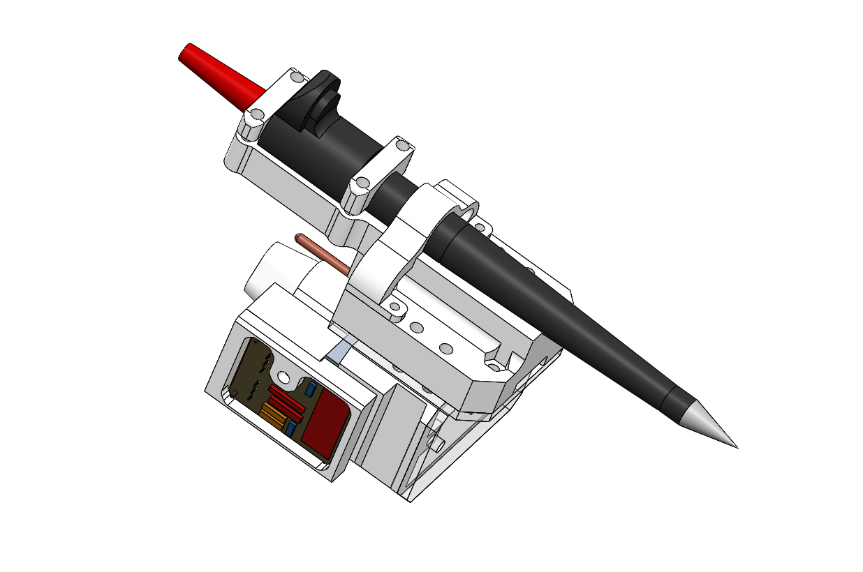
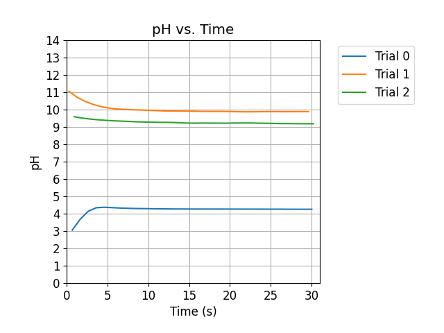
pH Probe
Probably the simplest tool. A pH probe for measuring pH. I got the probe from Atlas Scientific, along with the breakout board that I could connect directly to my TOSLink transceiver. I made a clamping mount for the probe. The wire it came with was quite long, so I cut it and spliced it carefully after cleaning it (because I’ve had problems in the past with data transferred over solder joints).
Streamlined PID Tuning Procedure
Marc and I wrote a paper about a streamlined PID tuning procedure for flexible base manipulators like the robotic arm mounted on our rover with suspension. The paper got accepted into IROS. Essentially, we came up with a Lyapunov candidate function that allowed us to figure out what PID gains to choose and for which states our system was stable. If you’re interested, check out the paper below!
Paper is here: