‘Barrel Roll’ Flagship Battlebot
This project served as my pinnacle achievement during the 2016-17 school year. As ASME’s Battlebots Lead, I took on the ambitious task of creating a never-seen-before battlebot. As a member of a team of six individuals and under the guidance of our project lead Sean Oh, I designed 90% of the robot and conducted around 60-70% of the entire manufacturing process. In doing so, my hands-on skills in this field of mechanical engineering greatly expanded as my comfort with large scale and high precision machining increased substantially.
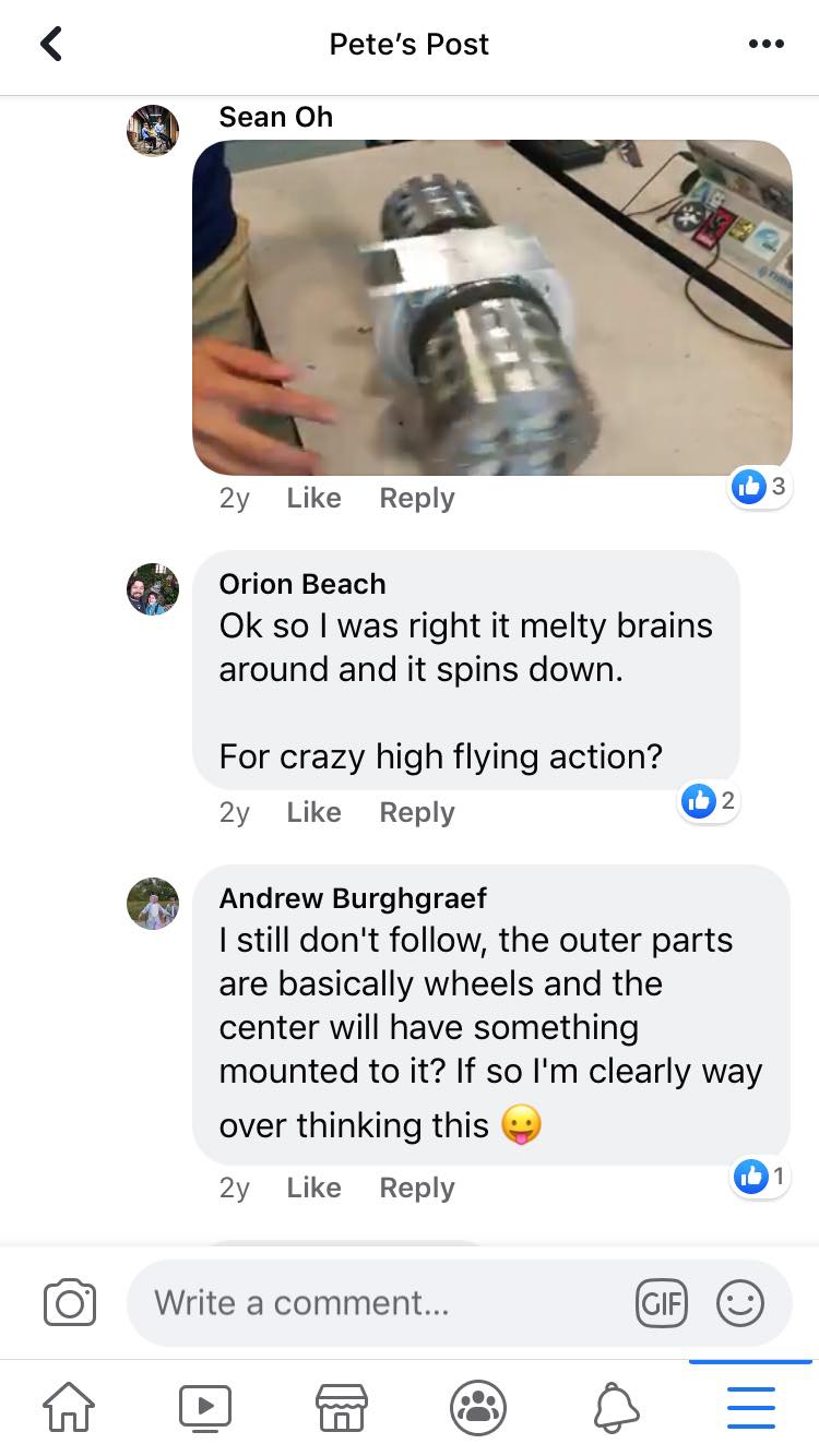
“Thwackbot” Concept
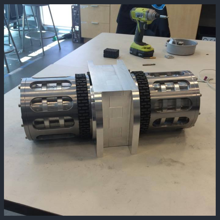
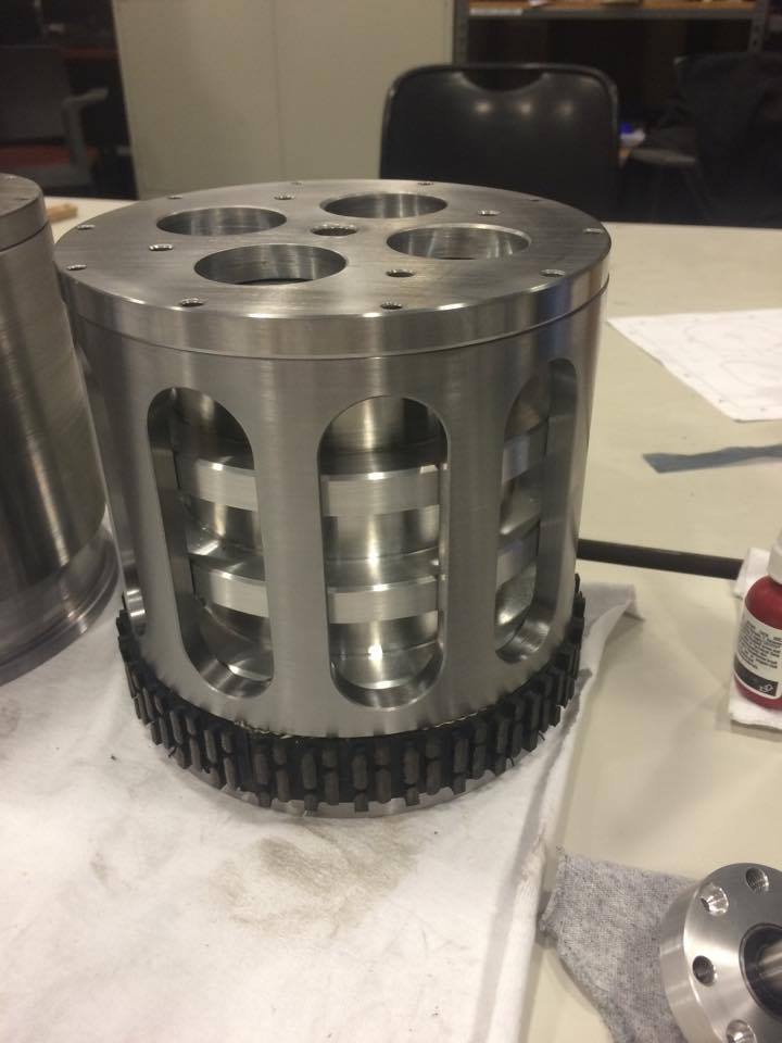
Barrel Roll boasts two cylindrical arms rotating about shafts that protrude from the box-shaped middle body that housed the electronics. Upon spinning these arms—which had built-in treads—in opposite directions, the entire robot would spin in a circle, threatening to dangerously impact oncoming bots. Each arm consisted of an aluminum core and steel shell with treads for traction.
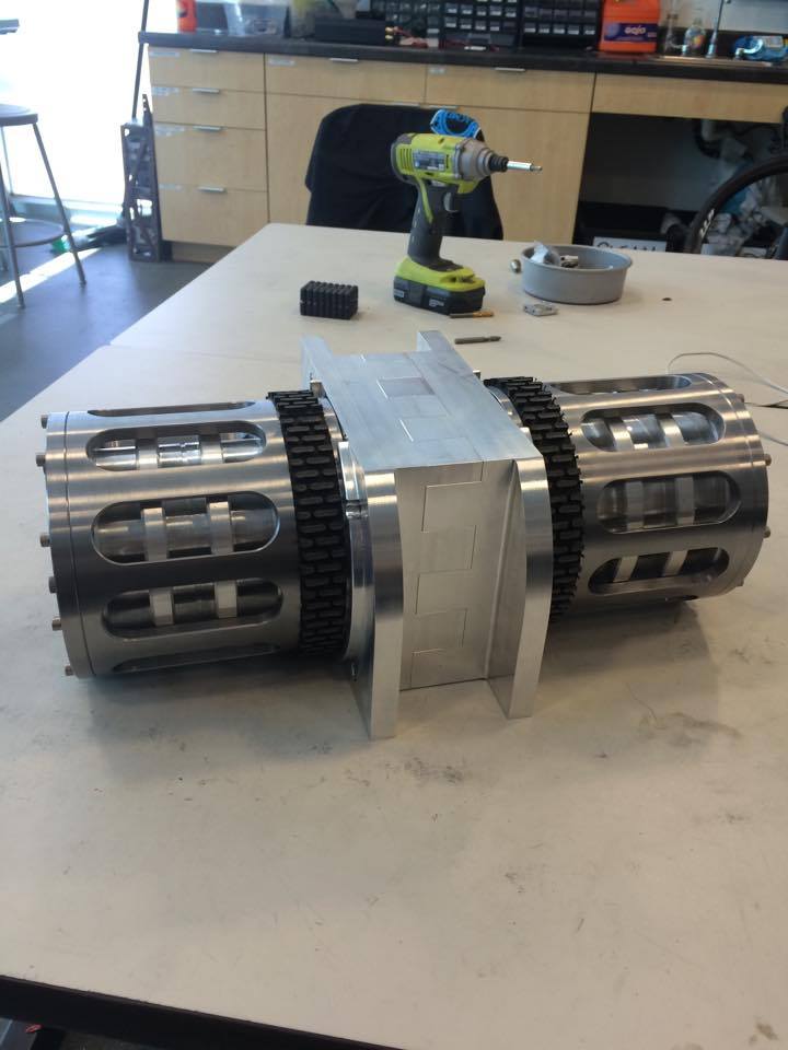
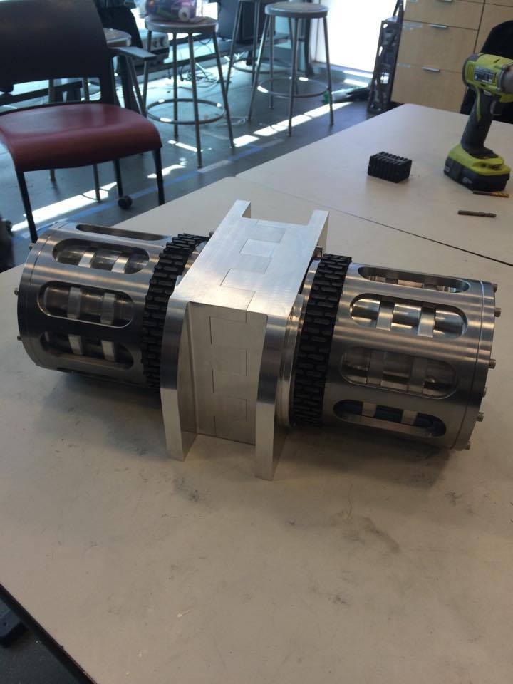
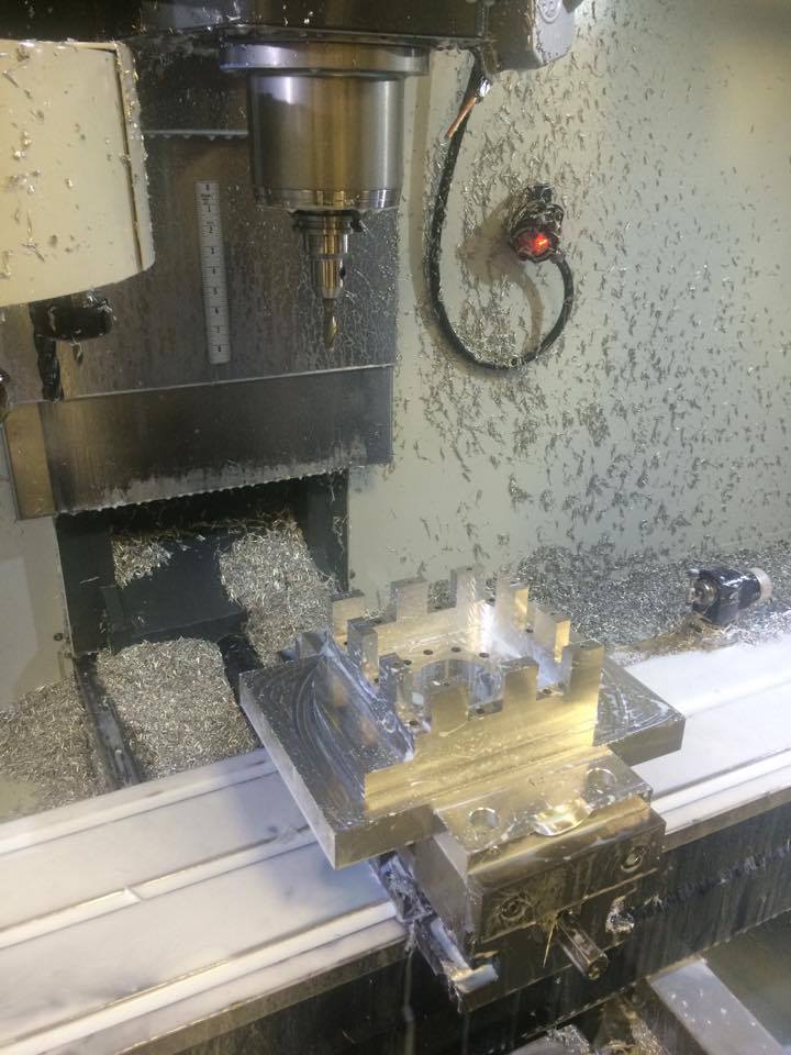
Middle Body Junction
The junction between the two middle body halves resembled a jigsaw pattern, with each tooth on one half fitting tightly into the respective gap on the other half. Upon impact normal to one of the cylindrical arms, this junction design would distribute the load among the teeth rather than on screws. The wedges on this middle body prevented the middle body from rotating due to the motors (instead of the arms). They were designed such that if the robot landed on the wedged sides, the center of gravity would always be beyond the point of contact with the ground so the robot would right itself naturally.
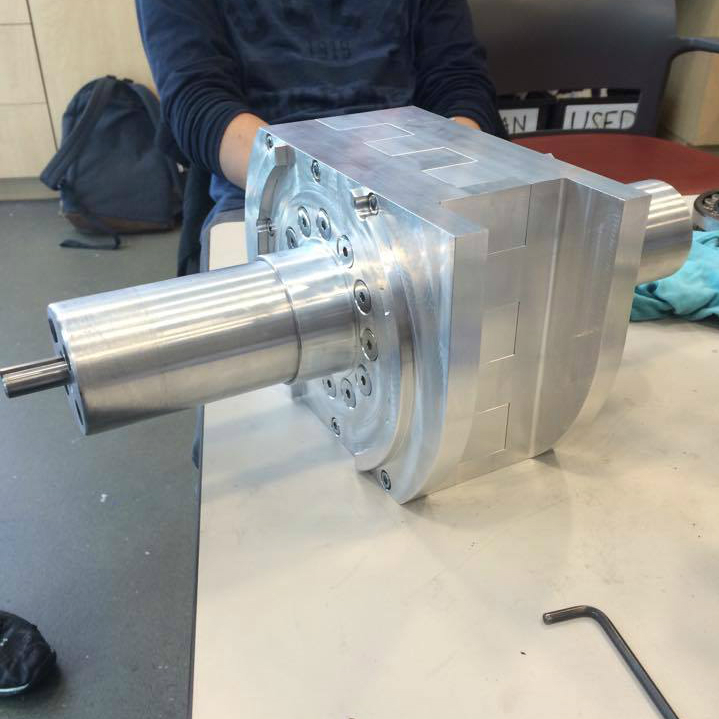
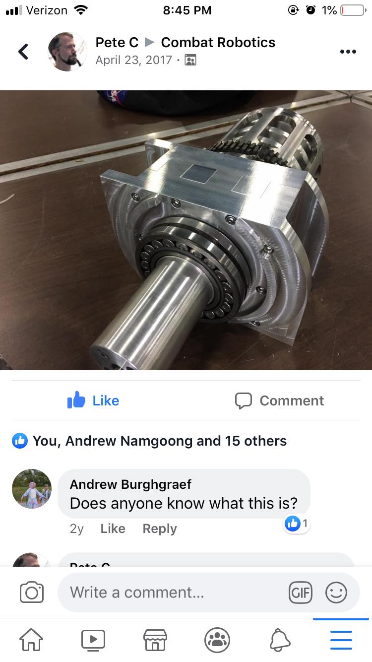
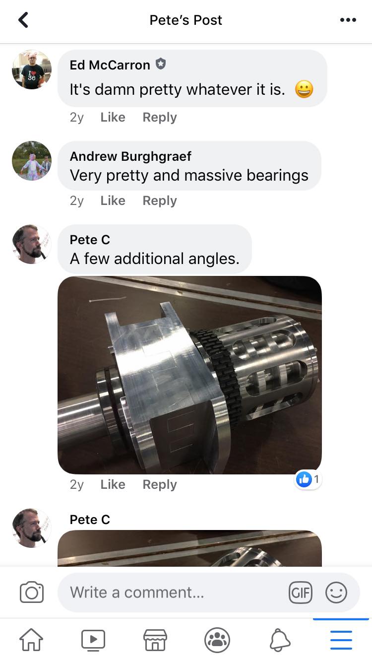
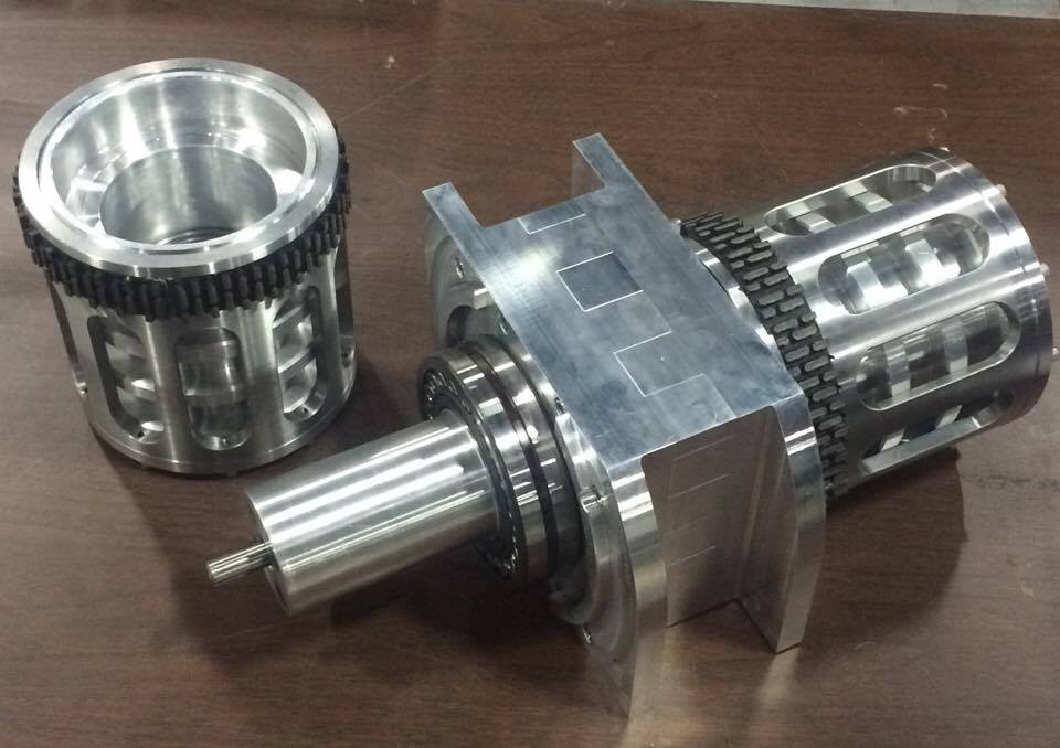
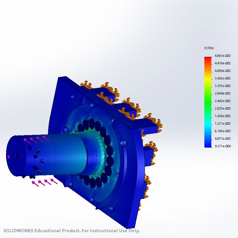
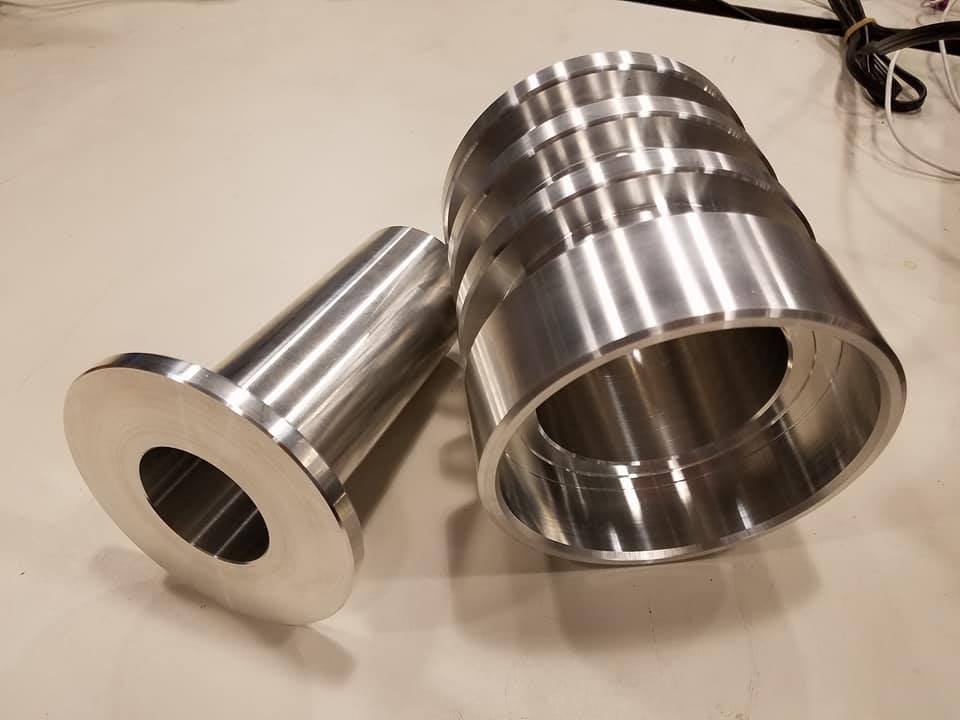
Inner Shaft
The inner shaft about which the steel shell and aluminum core rotated was as long as possible and housed the motor and gearbox. As a result, the exposed length of the motor output shaft exiting this inner shaft was minimized, hence reducing the torque and chance of breakage upon collision (as shown in the simulation).
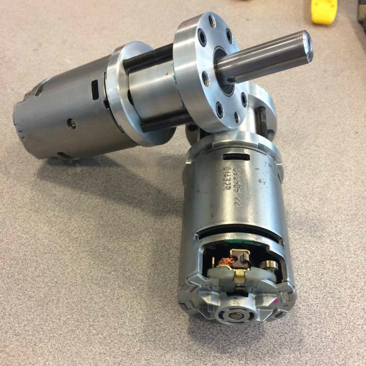
Motor and Gearbox
The motor and gearbox were selected carefully to achieve comparable impact energy seen in other battlebots while the robot was spinning at full speed. The outer casing was modified and CNC’ed to fit in the inner shaft and account for centripetal forces. The robot itself was driven by a “melty brain” control system, which essentially allowed the robot to translate linearly across a surface while spinning.
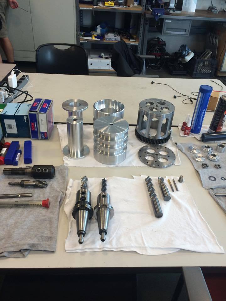
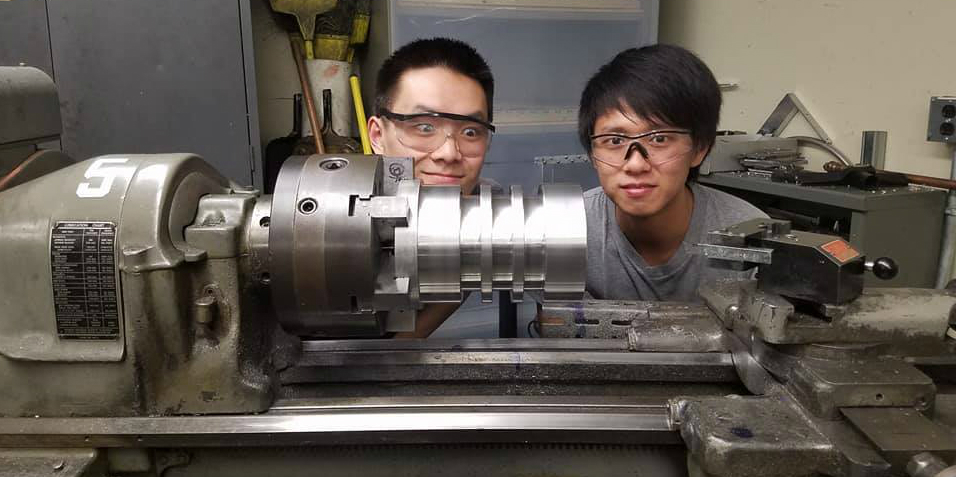
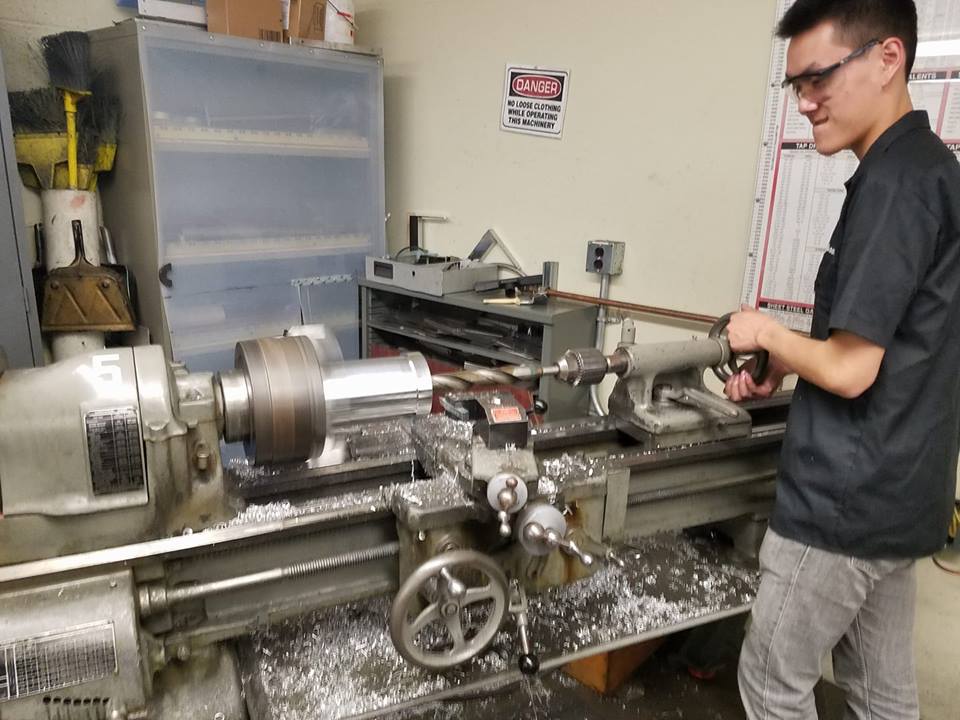
Manufacturing
Manufacturing was done on a manual lathe and a Haas CNC. Tolerances were held to ±0.0005 inches for press fits and +0.002 for slip fits. Large spherical bearings supporting up to 50000 lbs of dynamic load and needle roller bearings allowed free rotation and resisted radial forces. 4140 steel and 7075 aluminum were used to maximize material strength while remaining below the weight limit. Various processes such as boring, autofeed turning, and slot milling were employed to machine the parts.
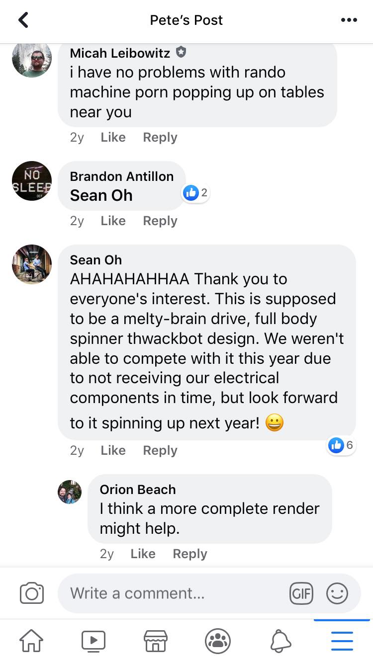
Community Response
The battlebots community responds: