CLIMR: Cabled Limb Interlocking Modular Robot
Two separate works have been submitted to IEEE Robotics and Automation Letters (RA-L) and the 2025 European Conference on Mobile Robots (ECMR).
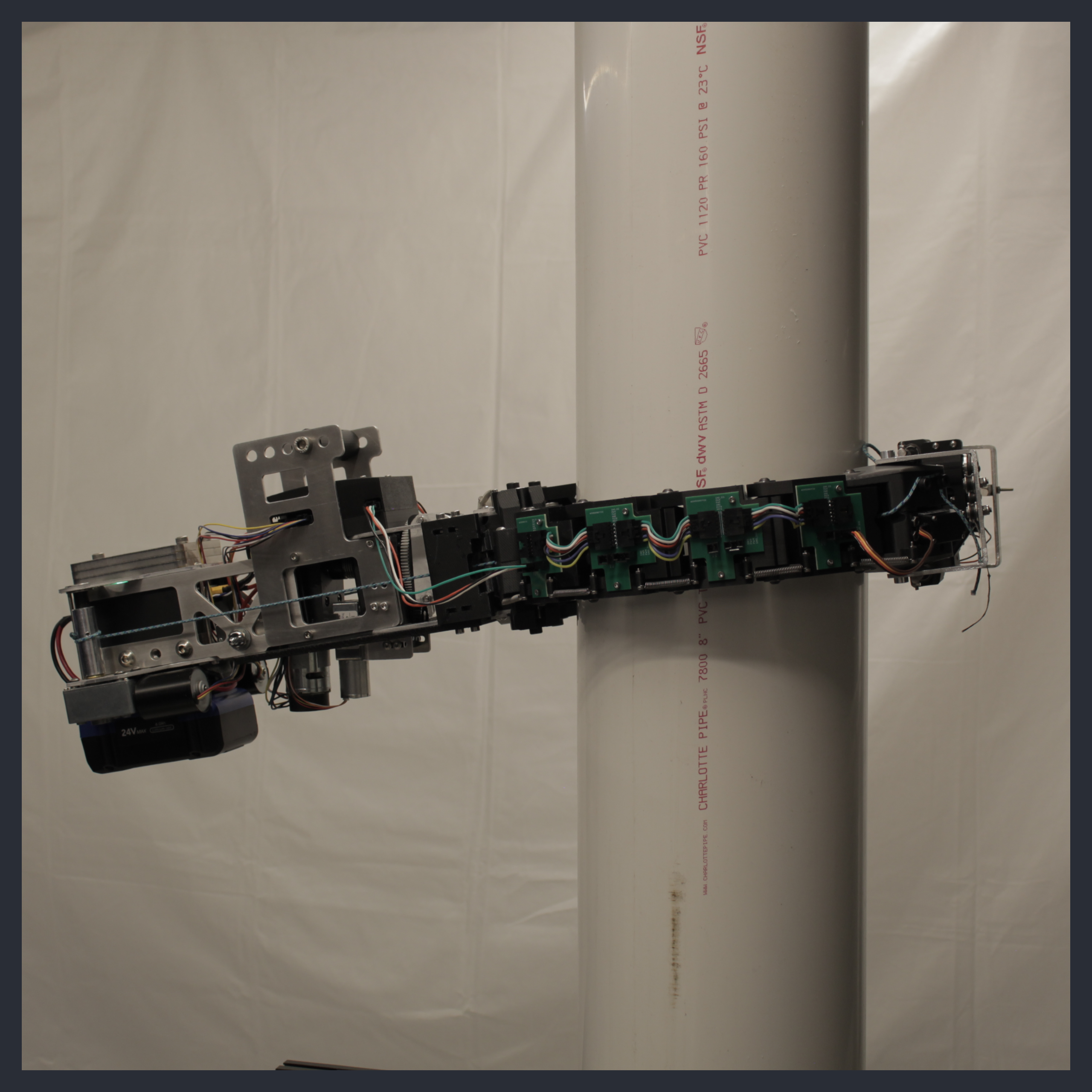
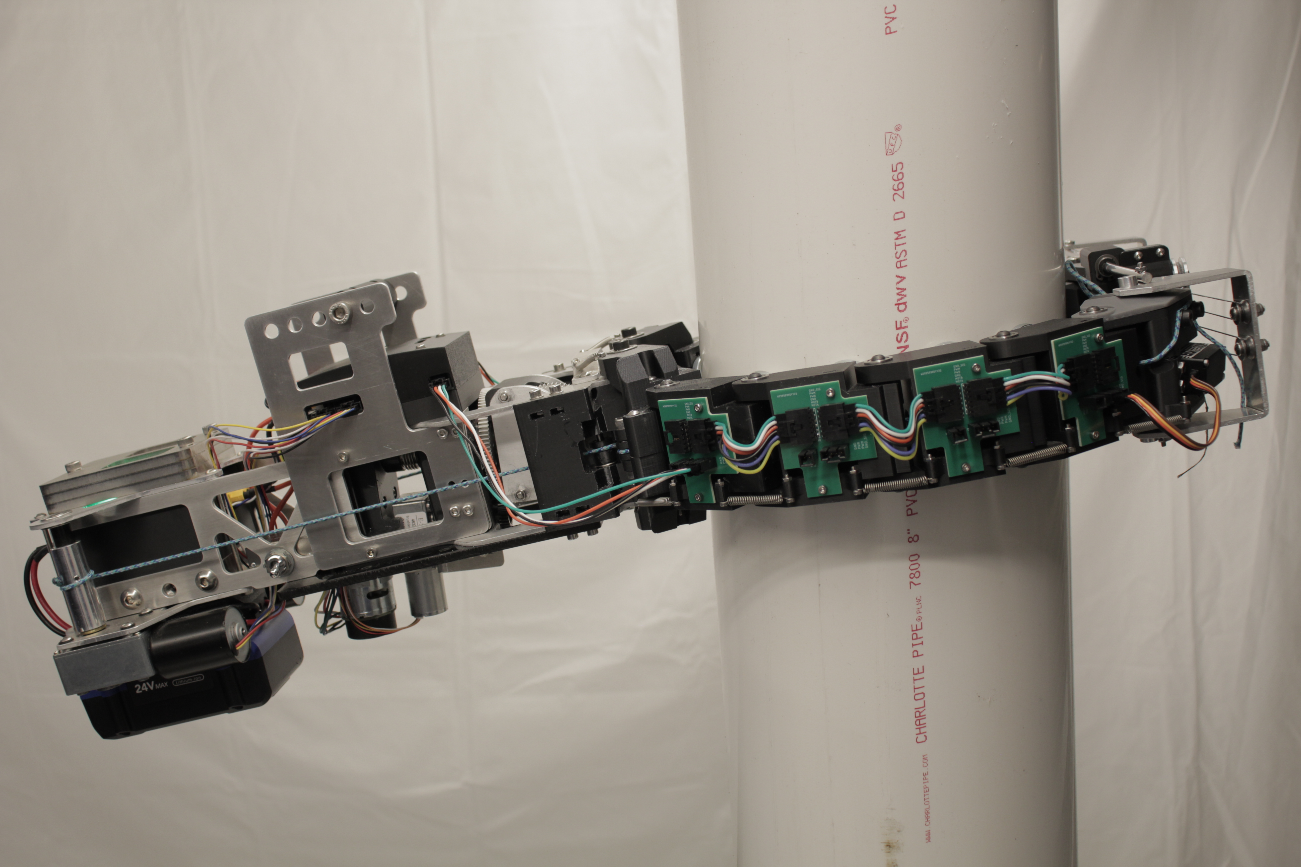
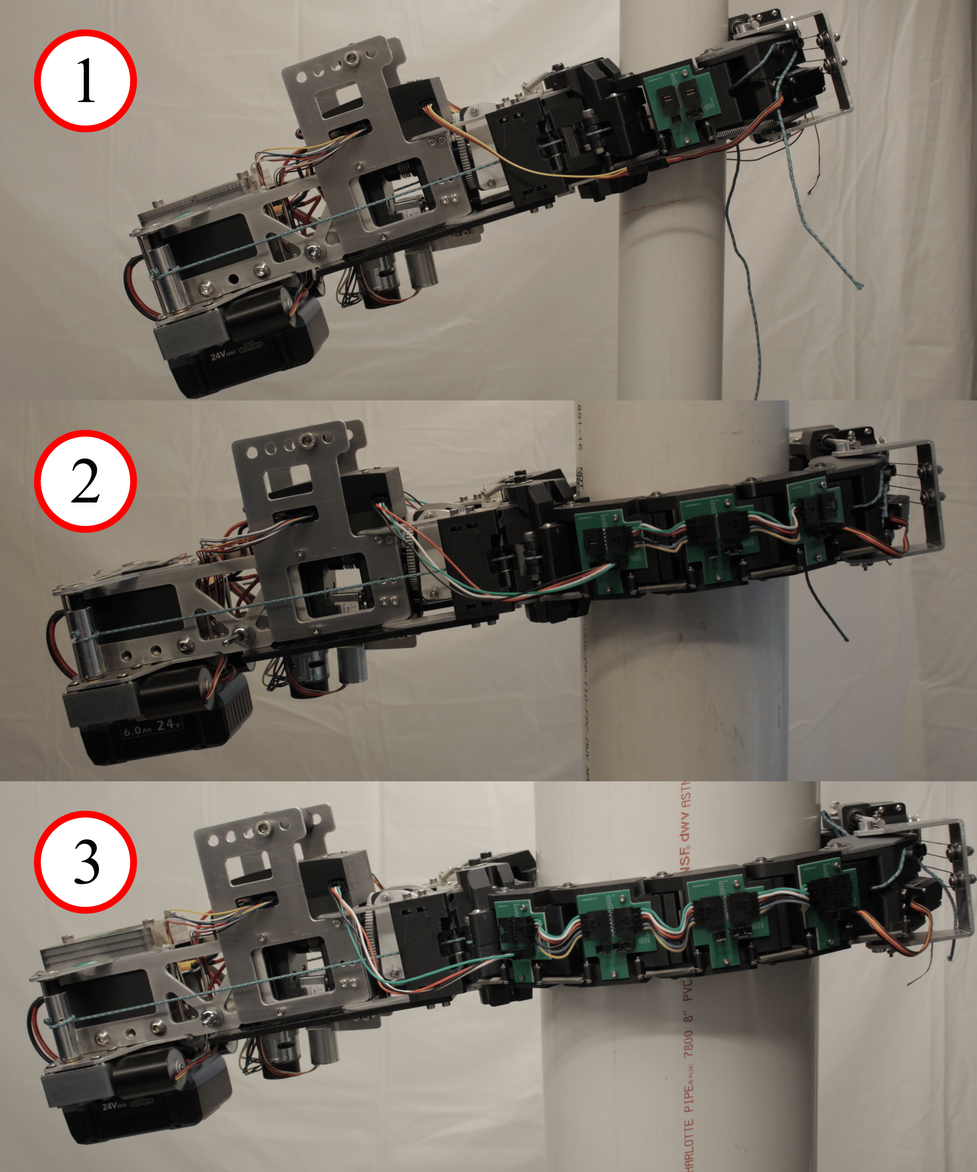
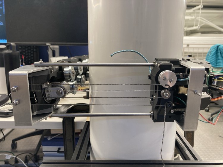
This robot is designed to climb poles and trunks (I use “columns” as a more general term). Essentially, this robot has two grasping arms that can autonomously wrap about a column. An automated latch at the end of one arm hooks onto the end of the other arm. Each arm is made up of modular links and is driven by a single tendon string that runs through them all. The number of links per arm can be adjusted to adapt for different column diameters. To achieve self-locking on the column (meaning the robot stays on the column when all electronics are off), the center of mass is designed to be off to the side of the column via a cantilever tail, generating a moment that creates a frictional force from the wheel pressing against the climbing surface. The drive wheel is mounted on a turret that rotates to achieve both vertical climbing and rotation about the column.
On the electronics side of things, I have a Raspberry Pi 4B running Ubuntu and ROS 2. This talks with a Teensy 4.1 mounted on a custom PCB with motor drivers and buck converters to control the various motors and servos on the robot. Lots of modeling was done for this robot, but the development revolved around extreme rapid prototyping because many features were difficult to model for. There were some semesters and summers where I was building a brand new robot every two weeks for testing!
Video Breakdown
This 4-minute video gives a breakdown of the robot’s features and functionality.
Design Constraints and Functional Requirements
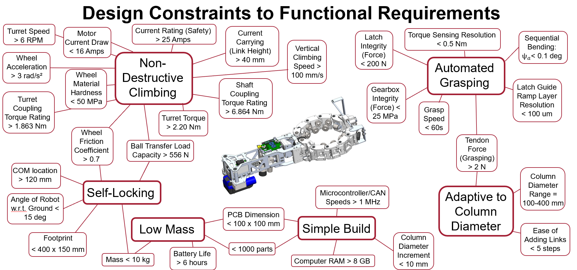
The general design constraints were formed from the commonly desired features found across past climbing robot research works and are tabulated below.
| Constraint | Reasons |
|---|---|
| Low Mass | Reduce drive power consumption and overall cost |
| Simple Build | Lower complexity generally means low risk of breakage |
| Non-Destructive Climbing | Climbing surface typically hard to puncture, surface damage undesirable |
| Self-Locking | Safety, can commit all power to payload |
| Automated Grasping | Removes need for human assembly before climbing |
| Adaptive to Column Diameter | Broadens variety of tasks, allows frequent climbing, limits max column diameter |
From here, a list of guiding functional requirements could be devised. While these weren’t set in stone, they gave some metrics when it came to selecting things like motors, materials, and part dimensions.
Spreadsheet of functional requirements can be found here: Download Excel Document
Self Locking Body
Design and Materials
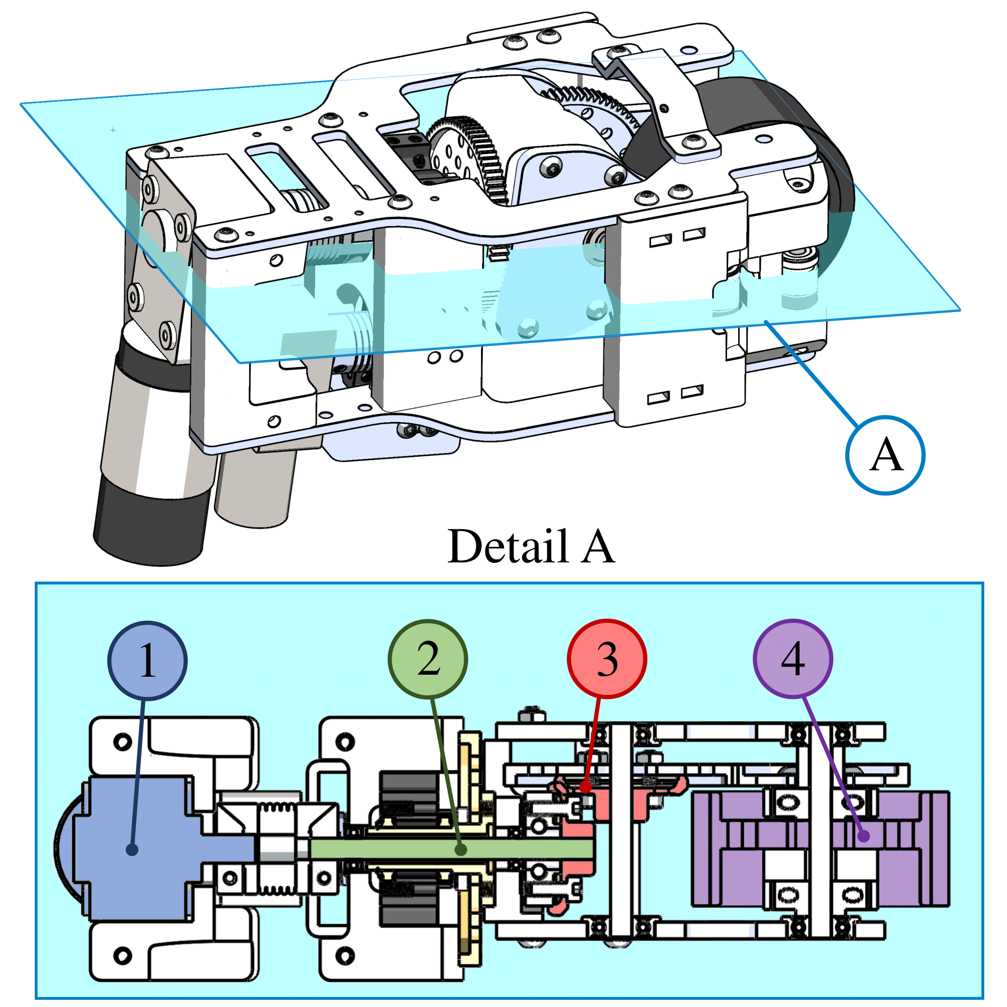
The main body houses the drive and turret motors. The drive motor (1) rotates a through-hole drive shaft (2), which moves the wheel (4) on the turret through a bevel gear transmission system (3). The turret itself is twisted by a brushless worm gear motor. The body is made of 3D printed PLA plastic and waterjetted 6061 aluminum components, primarily for their structural strength and relatively light weight. However, weight on the main body was not minimized, mainly because it assists in offsetting the center of mass for self-locking. Nevertheless, it was ensured that the main body was not too heavy for the drive motor.
The main body is attached to a cantilever tail to offset the center of mass away from the column axis. This offset creates a moment arm, which generates a normal force on the drive wheel and a frictional force that supports the mass of the robot when all the motors are off. The drive motor has a worm gearbox, which prevents backdrivability. The end of the cantilever tail has the Raspberry Pi computer, the tendon-driving motors, the Kobalt tool battery, and mounting holes for modular weight additions if needed.
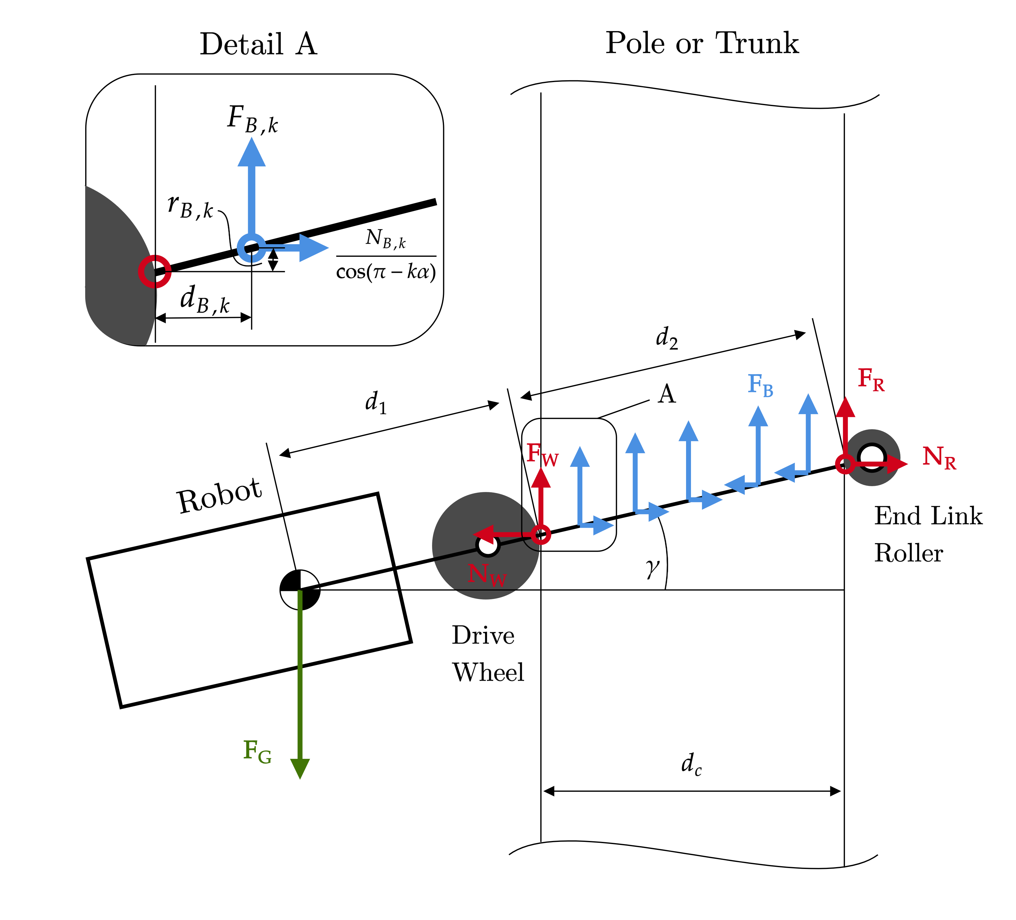
Kinematics and Statics Modeling
Finding the condition for self-locking depended on the force balance equation in the vertical direction and the moment balance equation about the wheel’s column contact point. This condition tells us the necessary distance between the center of mass and the column axis. On the actual robot, the center of mass can be shifted on the body using the modular tail weights and the arm link modules. It should be noted that solving for this condition is significantly easier if it is assumed that the ball transfer bearings do not have any friction (which isn’t true in reality). Because the distribution of force along the arms is nonuniform, the force and moment balance equations become incredibly complicated if ball transfer bearing friction is considered to be nontrivial.
Underactuated Tendon Driven Arms
Design and Materials
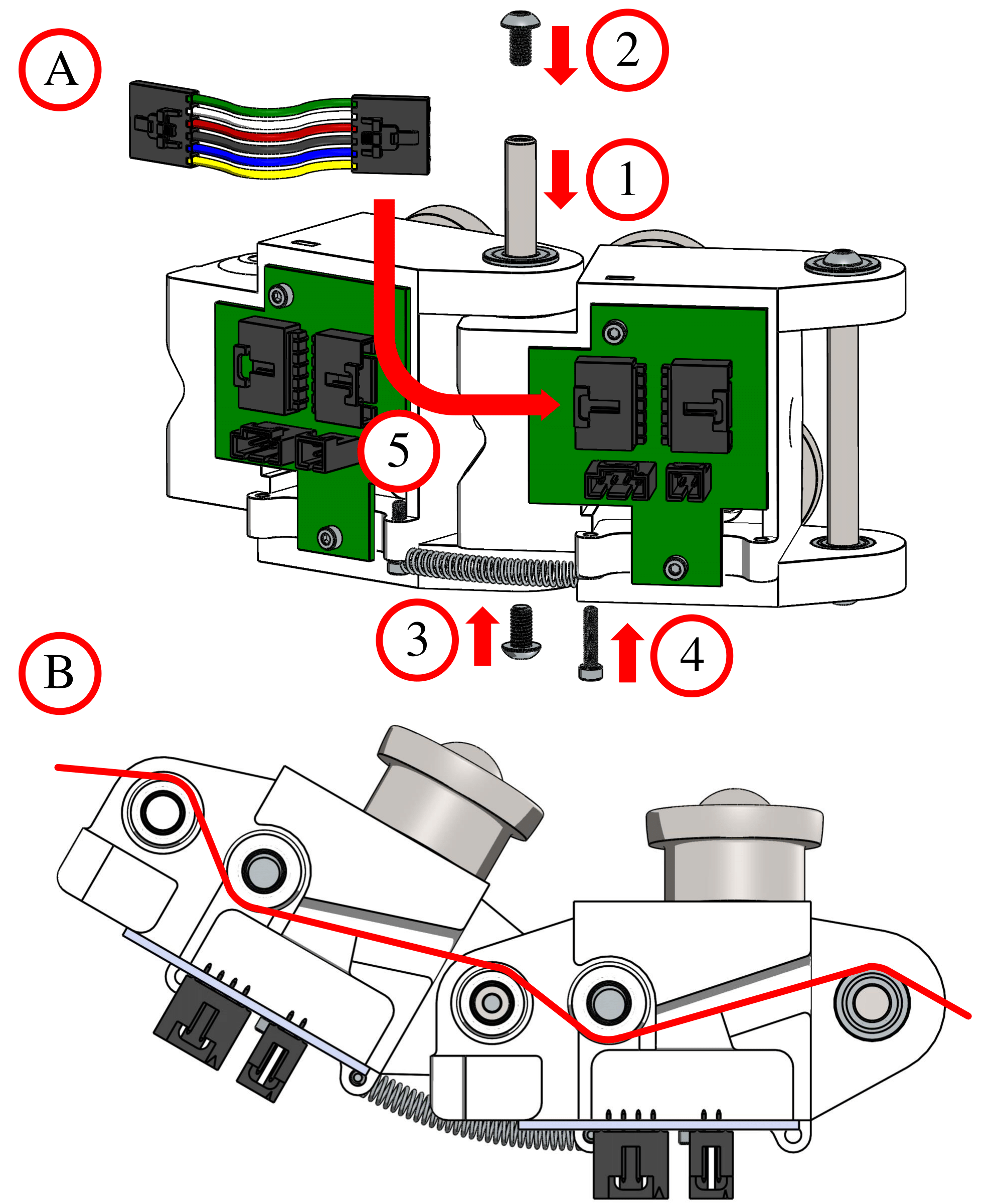
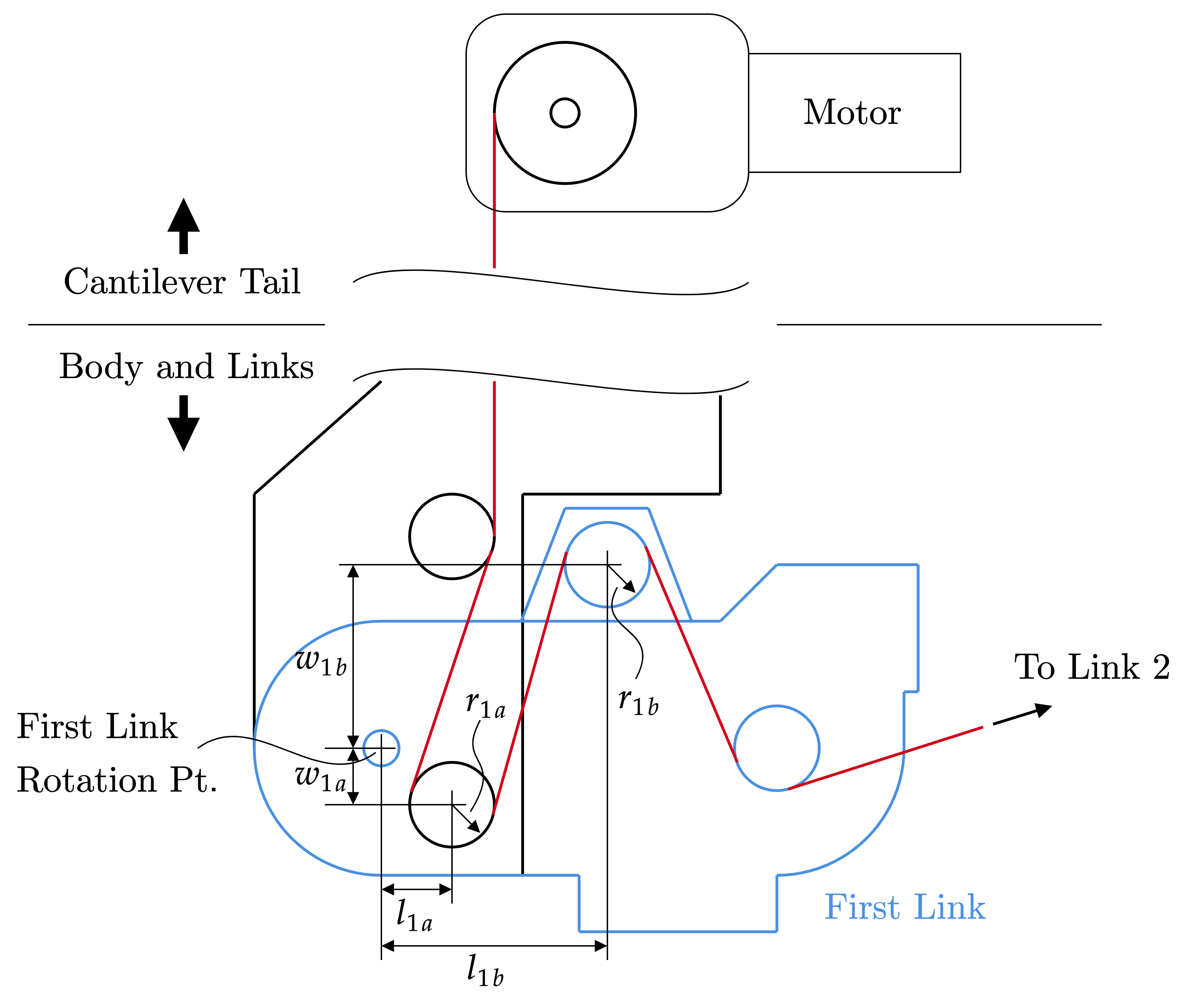
The grasping arms were made of modular links with a single ultra high molecular weight polyethylene (UHMWPE) tendon going through all of them. This was done to minimize the mass of the modular units, as the maximum climbable column diameter was dependent on the number of links that could be added and the maximum torque of the drive motor. Furthermore, the tendon-driving worm gear motors could be placed on the tail to facilitate self-locking. To add links, first the rotation pin and retaining screws are inserted (1-3), followed by the electrical connection (4) and the antagonist spring (5).
.jpg)
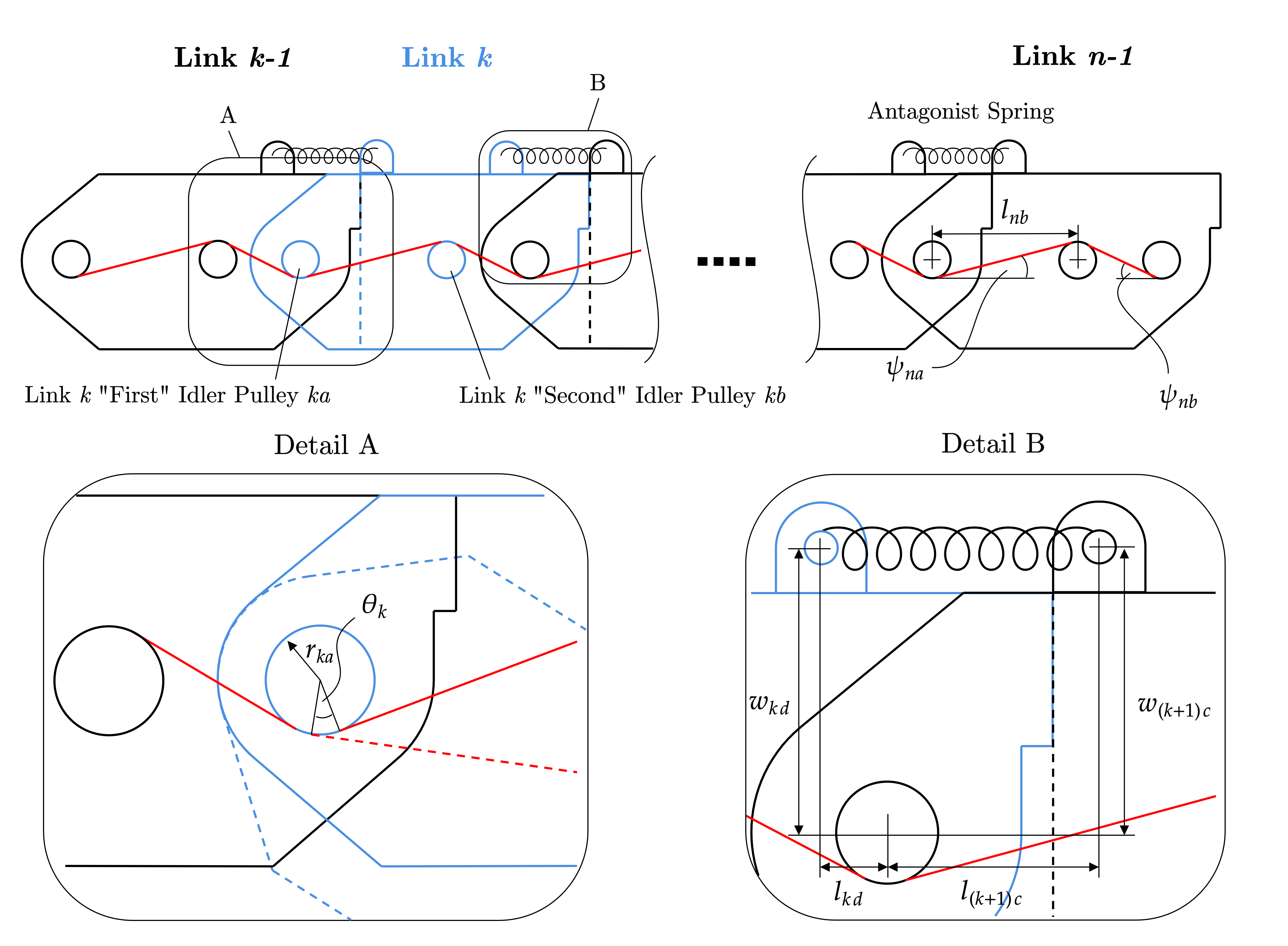
Each link is connected by a rotating pin joint. To enhance stability and improve contact with the column, each link is equipped with two steel ball transfer bearings. These bearings reduce sliding friction that could impede climbing forces, with at least two ball transfers per link necessary to ensure that the link maintains its proper orientation when the tendon tightens during grasping. The tendon is routed through each link using small idler pulleys, which help minimize friction along the tendon path. The arrangement of the pulleys facilitates sequential bending, ensuring that each link only bends once the preceding one has fully bent. The end links are secured with serrated flanged screws to anchor the tendons in place.
End Link Clutch Rollers
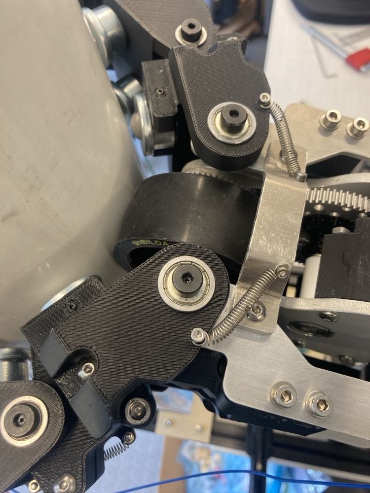
The end links were designed differently than the standard modular linkages. Because the normal force experienced by these links would be the greatest due to the moment created by the cantilever tail, links with standard ball transfer bearing contacts would experience excessive amounts of friction that would inhibit climbing. As a result, these end links has unidirectional clutch roller bearings mounted on rotational stages actuated by high power 12V brushless servos.
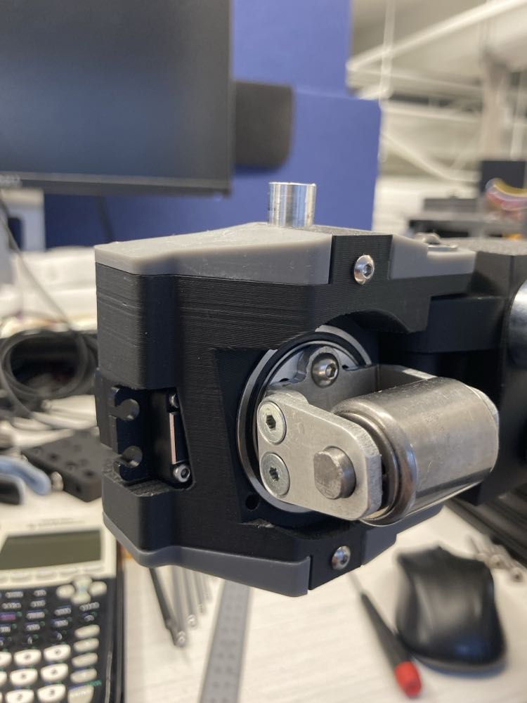
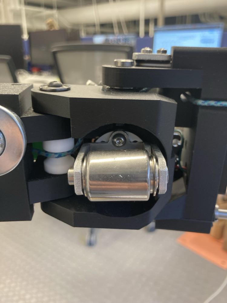
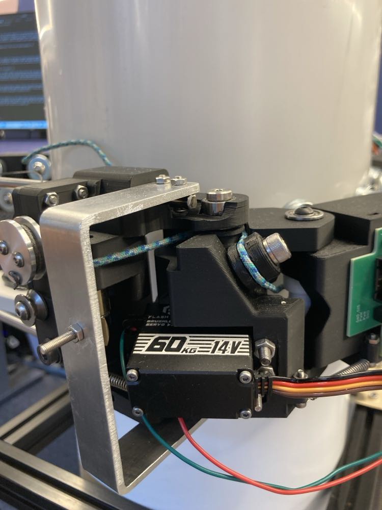
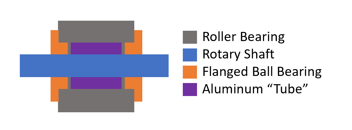
These clutch roller bearings assisted with self-locking due to their unidirectional nature while still producing low rolling friction despite the high normal forces. Mounting them was non-trivial, however, to ensure that there was minimal friction. In general, roller bearings do not support any loads in the axial direction, but they had to be constrained in the axial direction for this robot. To do so, the clutch bearings were mounted on a custom set screw shaft collar and D-shaft with a spacer and flange bearing at each end to both constrain the clutch bearing axially while also minimizing friction in case it slid to far to either side.
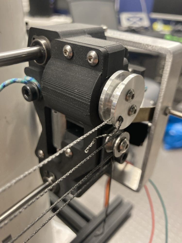
The Latch
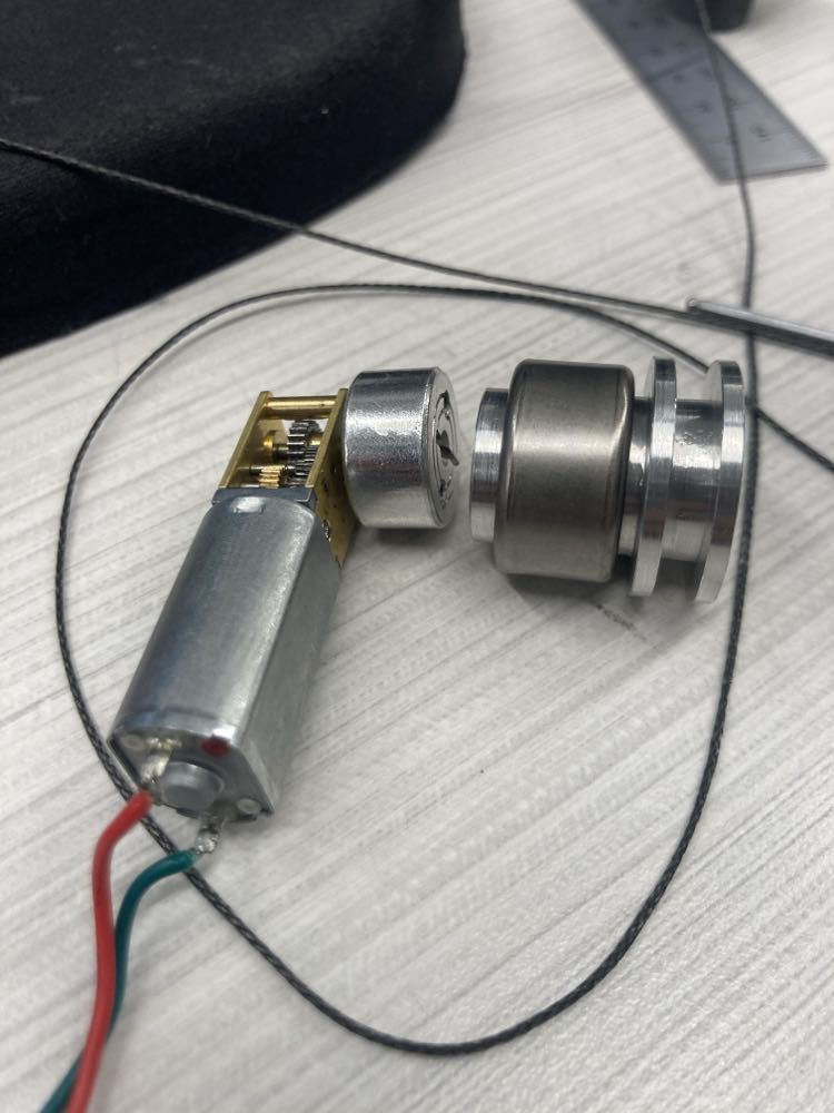
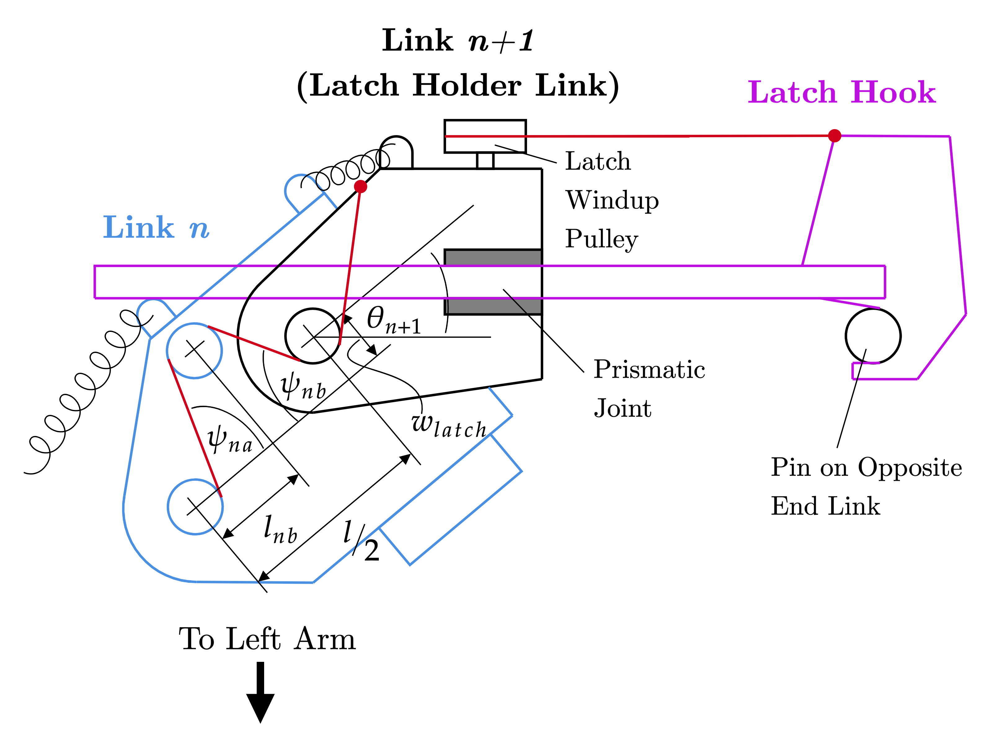
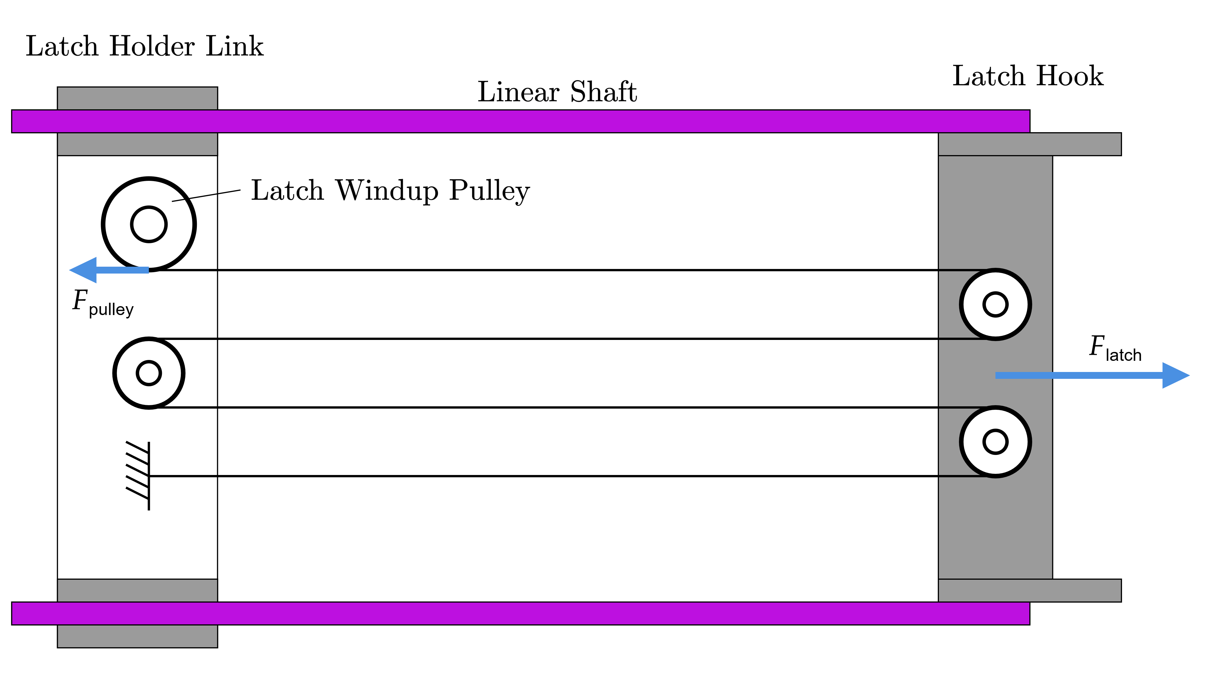
The tendons that pass through the arm do not generate enough torque at the joints to provide secure grasping around a column. Hence, an automated latch is attached to one end link. It is designed to hook onto a pin on the opposite end link, pulling the arms together for a more secure grasp before climbing. This latch consists of both a rotary joint and a prismatic joint. Once the arm links are fully in contact with the column, continued tension on the tendon causes the latch to rotate around its rotary joint until it aligns with the pin on the opposite end link. A 15 mm micro worm gear motor then pulls the latch along the linear shafts using a compound pulley system until the latch hooks onto the pin. A constant force spring provides the restoring force.
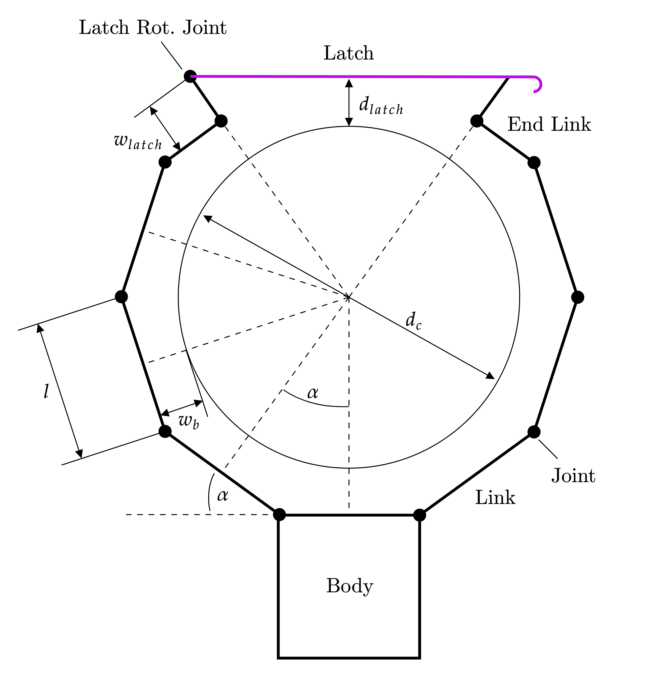
Kinematics and Statics Modeling
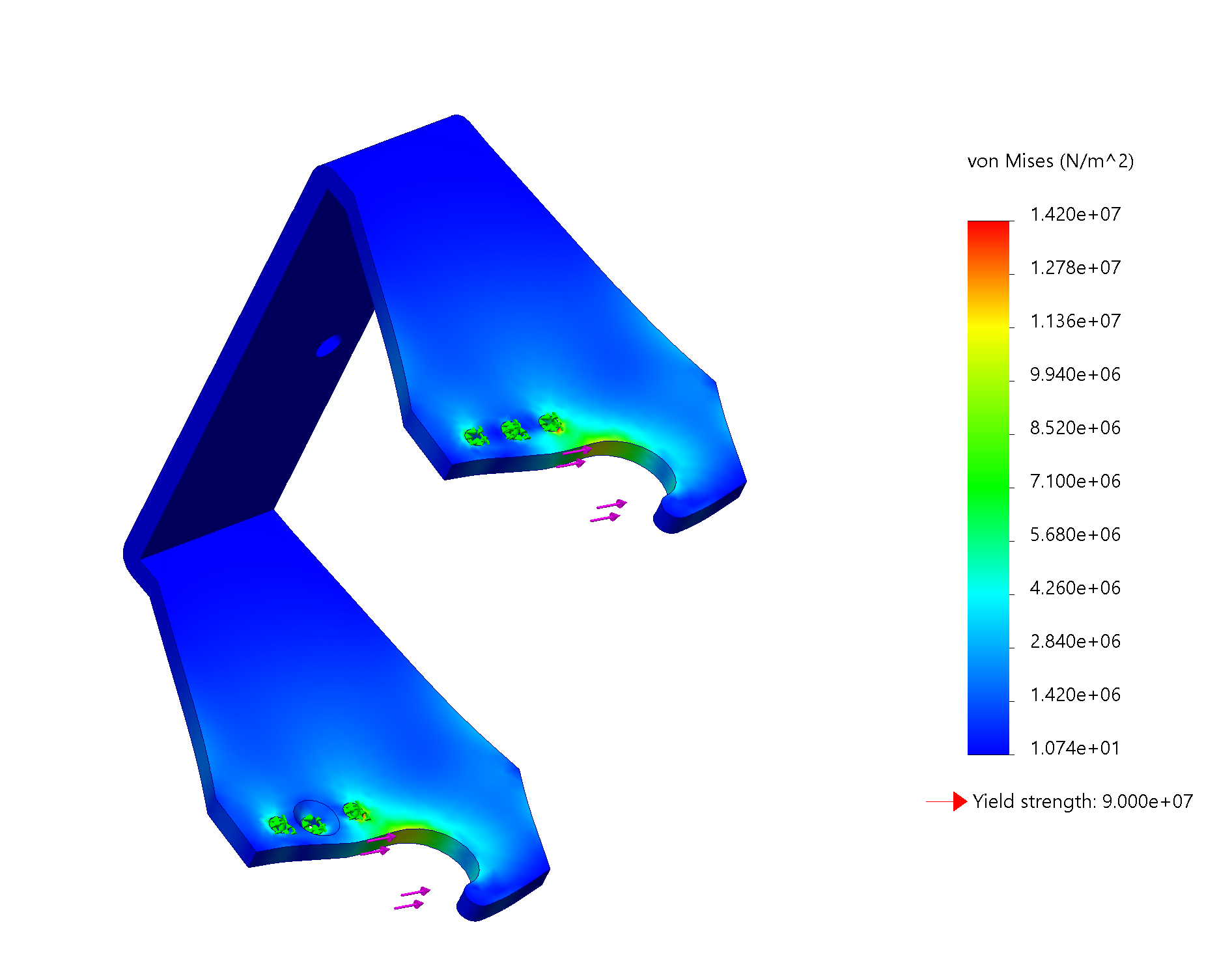
Modeling the arms in order to determine the amount of pulley windup required depends on extensive examination of the geometry of the links. On top of this, the amount of tendon stretch was also considered, assuming that the section of the tendon wrapped around the idler pulleys does not stretch. For the latch, calculations were done to ensure that the forces experienced by the latch do not break the small gears in the micro worm gear motor.
Drive Motor and Turret Motor Selection
Modeling
Selection of the drive motor was based on the desired acceleration of the robot. In this case, I wanted the robot to achieve a vertical speed of around 100 mm/s (which is comparable to other climbing robots) in 3 seconds. However, some things also had to be considered. The tangential drive force applied by the wheel could not be greater than the force of friction or else the wheel would start to slip. In the end, a 5840WG-555PM E-S Motors brushed motor with a 280:1 worm gearbox was chosen for the drive.
The turret motor was chosen based on the friction the motor would have to overcome. Because there is a large normal force being applied to the drive wheel due to the cantilever tail, the wheel presses up against the column, causing the rubber to deform and creating a rectangular contact surface. Assuming that the contact area was flat and not convex (which isn’t the case in reality), I could get a rough approximation of the friction by integrating across the contact area to get the total friction moment. I ended up selecting a 4632WG-2430BL E-S Motors brushless motor with a 600:1 worm gearbox.

| Motor | Required Torque (Nm) | Rated Motor Torque (Nm) | Rated Motor Speed (RPM) |
|---|---|---|---|
| Drive | 4.057 | 6.865 | 41 |
| Turret | 0.829 | 1.863 | 7 |
It should be noted that these calculations were generally done assuming that there was no ball transfer bearing friction. However, as explained in the submitted manuscripts, the statics and kinematics equations show that successful performance of CLIMR hinges on the balance between self-locking and climbing ability. I had to make sure that the center of mass was far out enough that the self-locking condition was satisfied but not so far out that the normal force on the ball transfers is increased (which in turn increasing ball tranfer friction).
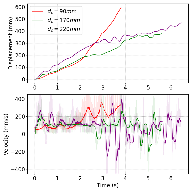
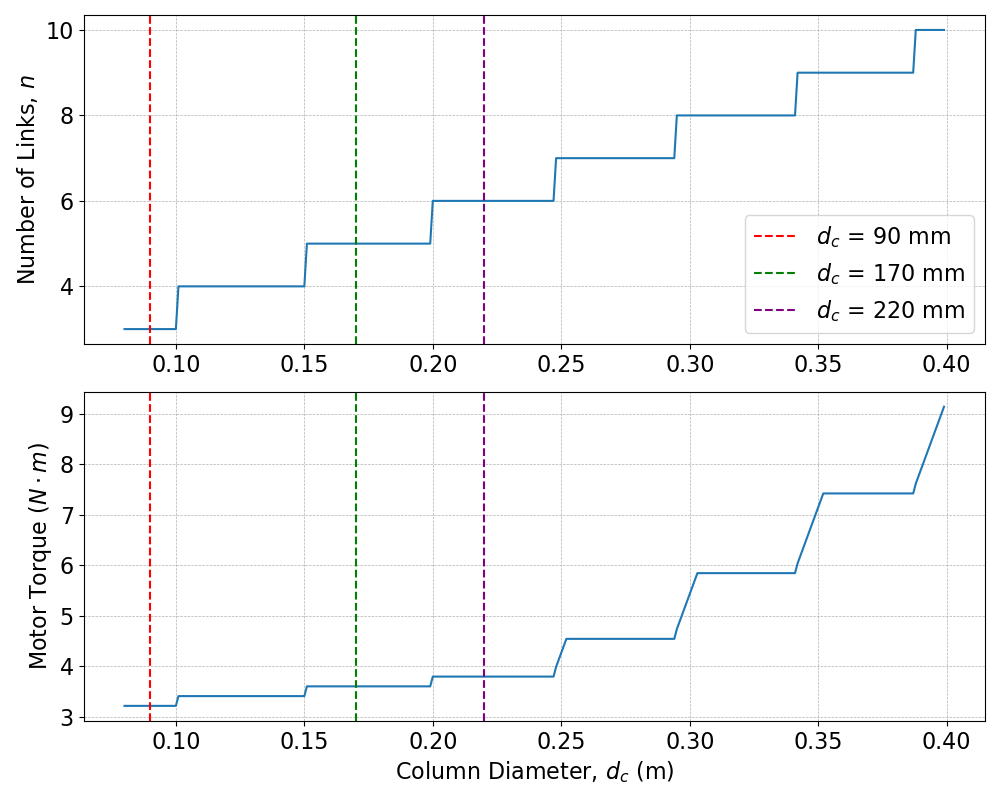
Maximum Column Diameter Limit
Despite CLIMR’s adaptability, there is still a limit to the largest diameter column that the robot can climb. Eventually, adding too many modular links and tail weights to the robot will cause the total mass of the robot to be greater than the available drive motor torque. Iterating over a series of conditional statements yields a plot of the necessary torque versus the number of arm links (or versus column diameter), which can be used as a metric to compare CLIMR to similar wheeled-grasping hybrid robots that are developed in the future.
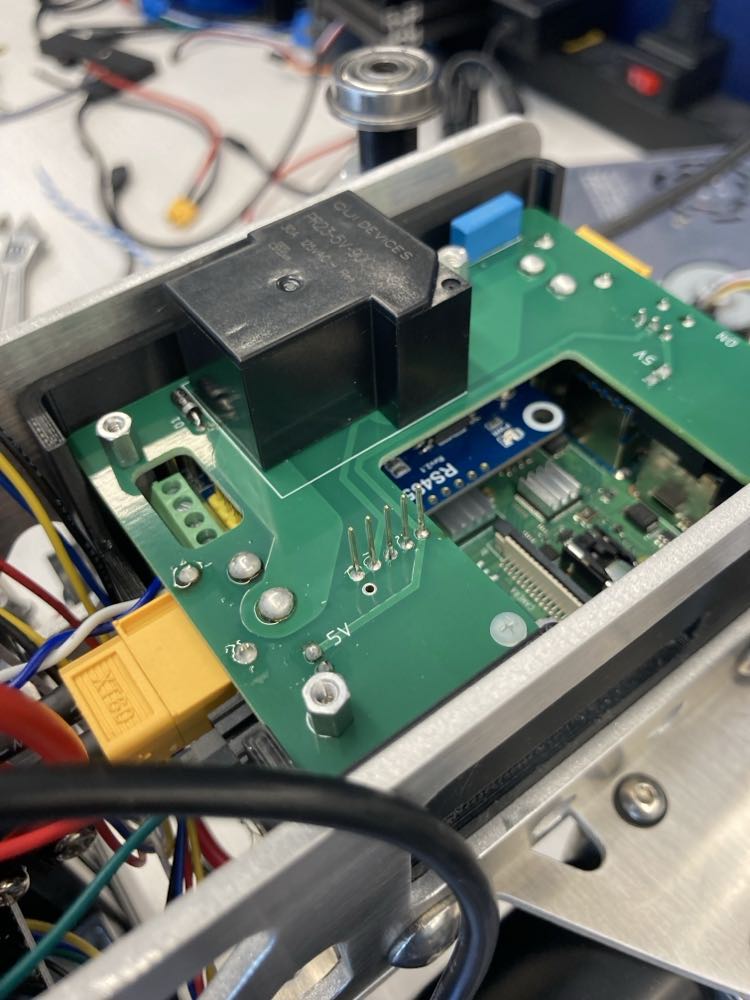
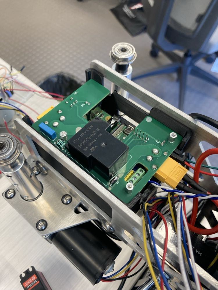
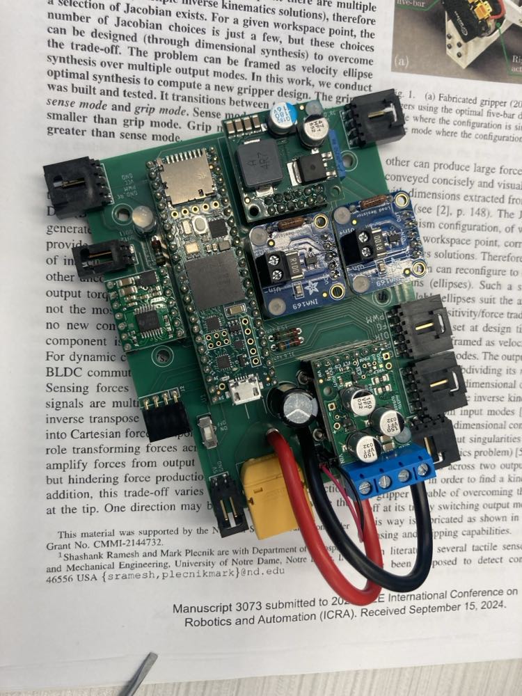
Main Body Microcontroller PCB
Design and Breakout Boards
How I usually design and package the electronics for my robots is creating a custom PCB on which I can mount many breakout boards and microcontrollers. I do this to get a balance of both prototyping speed and compactness. I’m a particular fan of Teensy 4.1 microcontrollers for their ridiculously high clock speed, many pinouts, and compatibility with the Arduino IDE. CLIMR’s Teensy 4.1 is mounted on the main body PCB, which also houses: a high power G2 18v25 Pololu brushed motor driver for the drive motor, an eletrolytic capacitor for PWM smoothing, two INA169 current sensors for the tendon motors, a 24V to 12V step down buck converter, a DRV8876 Pololu brushed motor driver for the latch micro worm gear motor, and an LED for visual cues. There is also a cooling fan for the G2 18v25 Pololu brushed motor driver.
Feedback Controllers
Most of the actuators are controlled using standard PID position controllers. However, the D terms were removed from the PI velocity controller of the drive motor and the PI torque controllers for the tendon motors, as feedback readings were affected by noise. The micro worm gear motor controlling the latch operates until a current spike is detected, signaling that the latch has successfully hooked onto the opposite end link.
Tail Electronics
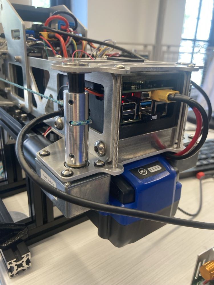
Raspberry Pi
The computer on the tail is a Raspberry Pi 4B. The operating system is Ubuntu, and I also uploaded ROS2 so I can have different nodes talk to each other in a modular fashion. Additionally, I overclocked the CPU for extra processing power (while making sure to have a fan and heatsinks, of course). The computer “box” houses three boards: the Raspberry Pi on the bottom, a CANBus hat on top, and a custom PCB on top of that. The custom PCB has the step down 24V to 5V buck converter that allows the Kobalt tool battery to supply power to the Raspberry Pi. To control the robot remotely, I just use Teamviewer to remote desktop and then access the terminal.
CANBus Commands and Packages
As mentioned, a CANBus hat is mounted on the Raspberry Pi. I chose to use CANBus to communicate with the main body PCB because of CANBus’s high data transfer rate as well as its modularity. In this sense, CLIMR is a robotic platform. With some easy design modifications, payloads modules can be both mechanically and electronically integrated into the system quite seamlessly because the infrastructure is there. CANBus messages sent along the wires are broken down by mailbox number. Drive wheel position, drive wheel velocity, right and left tendon torque and position, servo positions, turret position, latch control, and data collection are all potential commands.
Remote and Manual E-Stops
The custom PCB on the top of the computer box stack has the Raspberry Pi power switch and the buck converter. More importantly, it houses a high power relay for remote safety switching and an LED to indicate the on/off status of the relay. I designed the PCB so the pins aligned perfectly with the Raspberry Pi and CANBus hat header pins so that I’d be able to access the power and IO pins. For extra safety, I have a manual high power switch serving as an extra E-stop between the battery and all the motors.