Bairclaw Robotic Hand Expansion
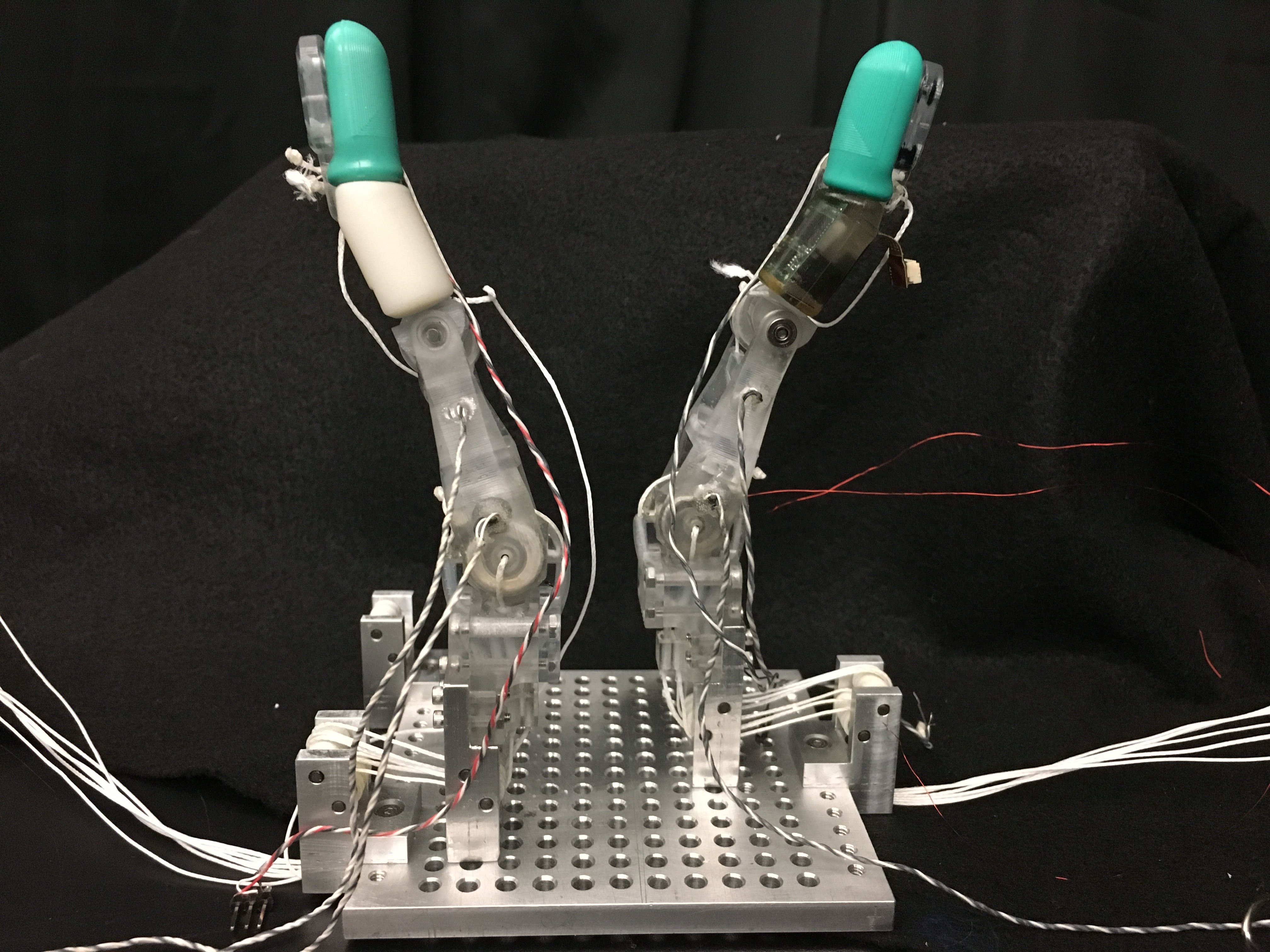
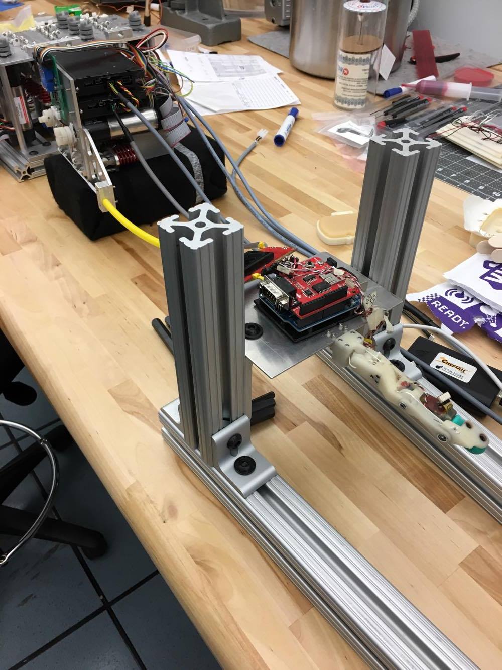
In the UCLA Biomechatronics Lab are Barrett Technology’s WAM robotic arm and tendon-driven fingers made by the lab for a prospective robotic hand, nicknamed the “Bairclaw.” My duty was to merge these two systems together with an adapter and expand the testbed from one to three fingers by building a motor bank.
Motor Bank
Expanding the Bairclaw System
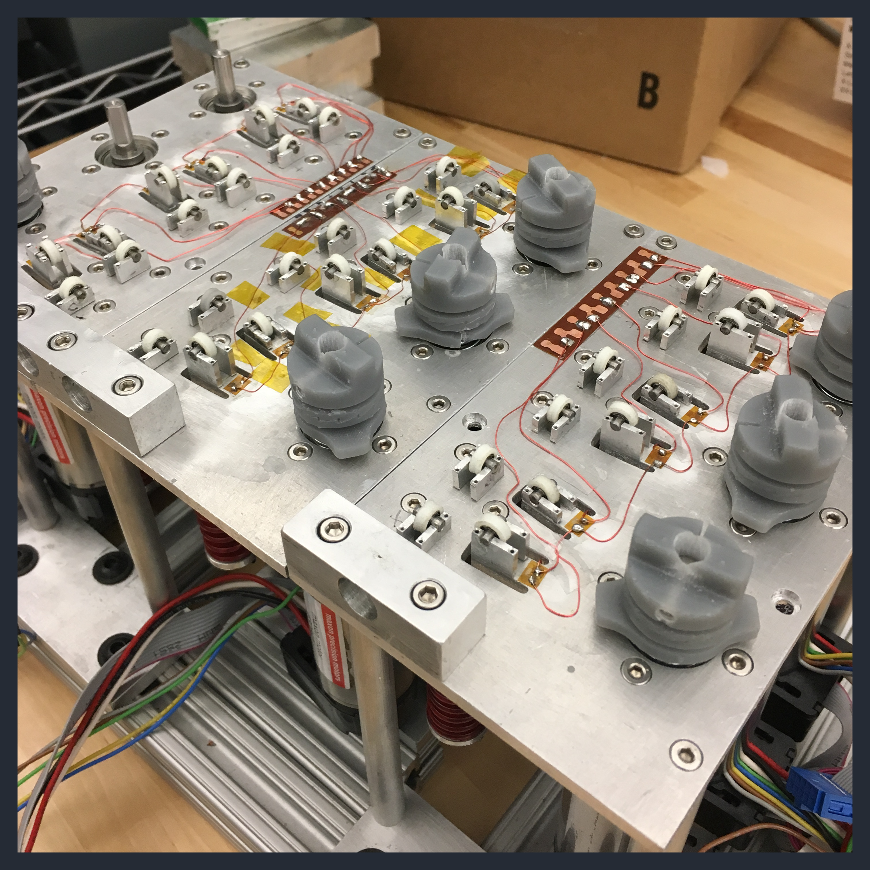
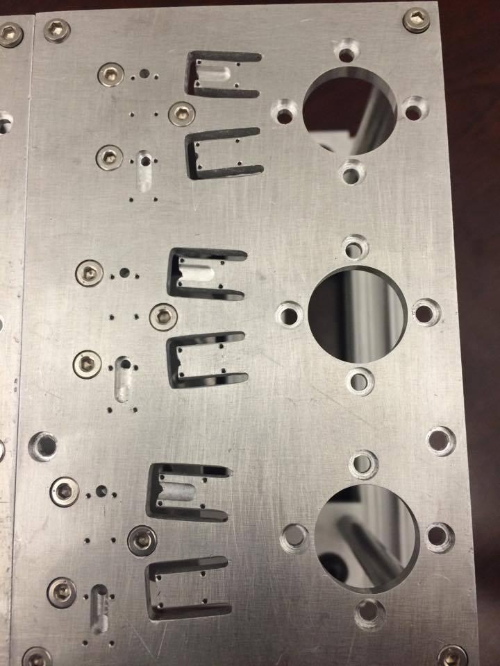
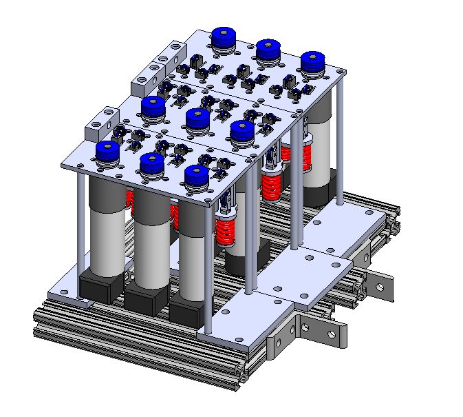
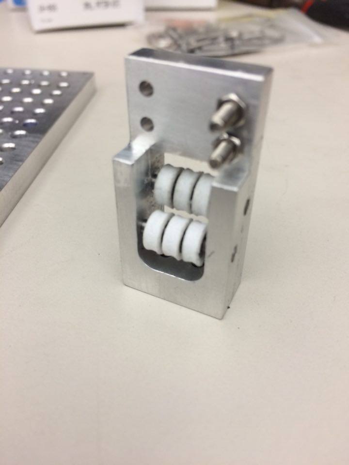
With three modular motor units, the motor bank was designed to accommodate 18 tendons for three fingers, which each had four degrees of freedom. Stepper motors in the bank controlled tendons. Pulleys redirected the tendons towards yellow vacuum tubes that housed six separate Teflon tubes through which the tendons individually traveled. Each pulley mount was only 1/16 inches wide, 3/8 inches long, and as small as 0.09 inches tall–a fairly tough machining challenge!
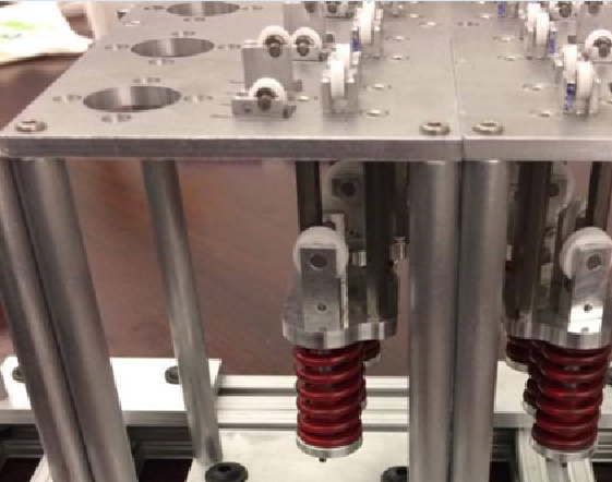
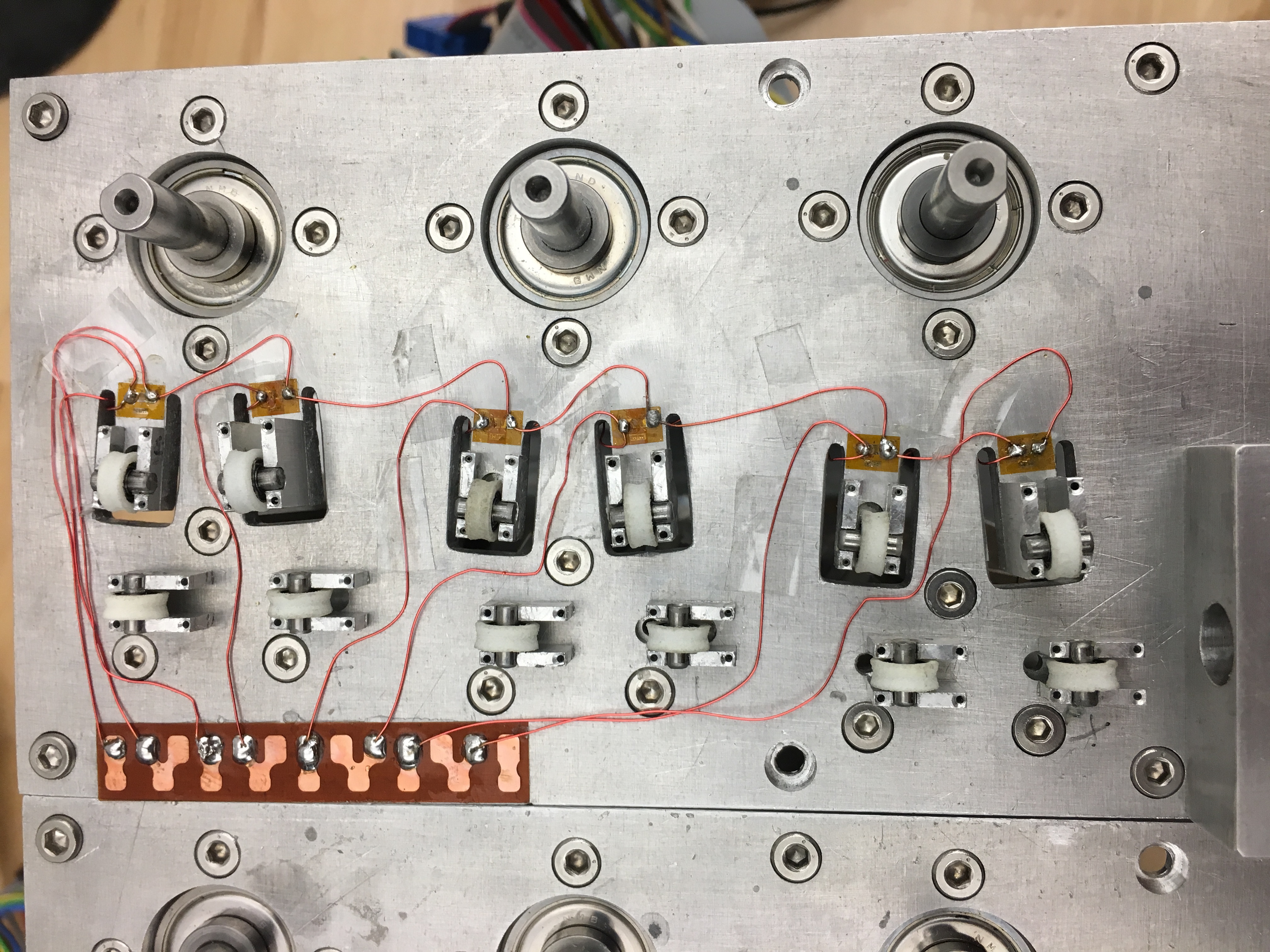
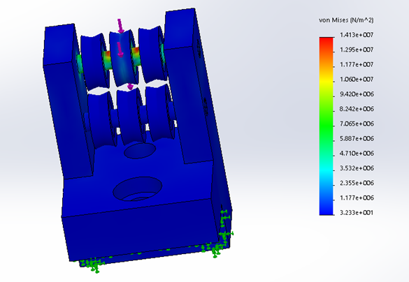
Springs and Cantilever Beams with Strain Gauges
Springs allowed the user to pre-load the tendons to prevent their detachment from the pulleys during operation. The tabs on which half of the pulleys resided acted as cantilever beams. Their deflection during operation could be measured by strain gauges and used to determine tendon tension.
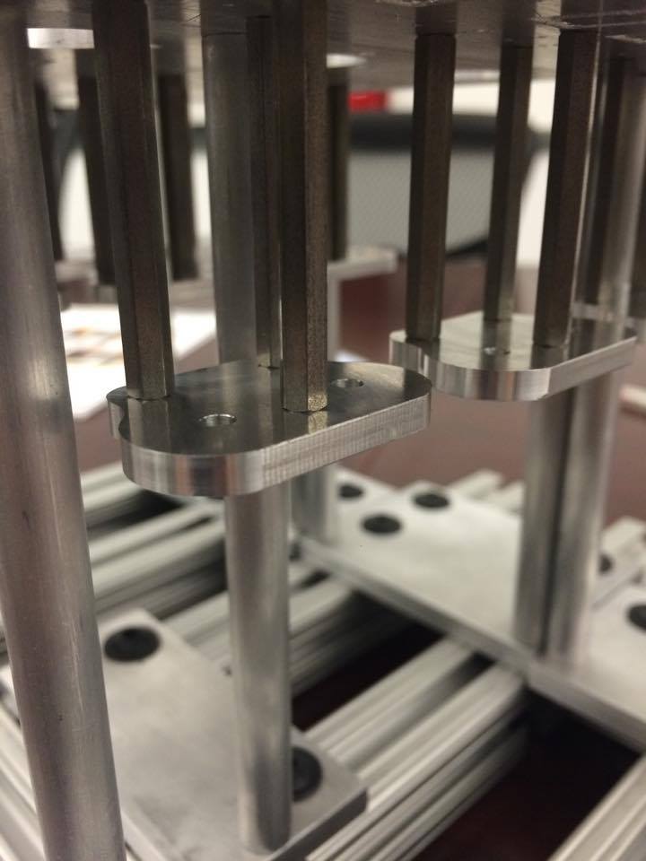
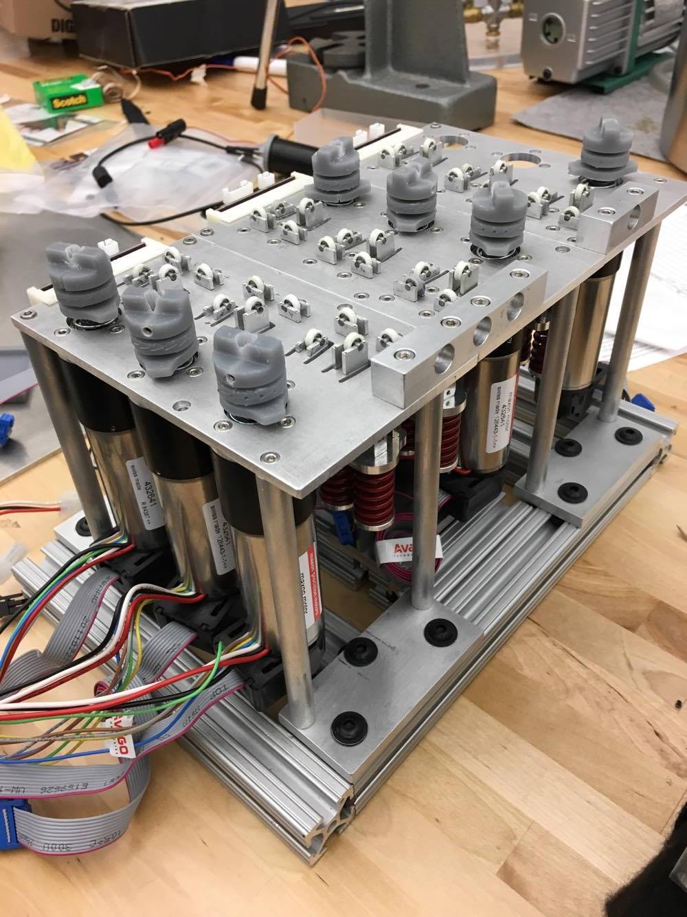
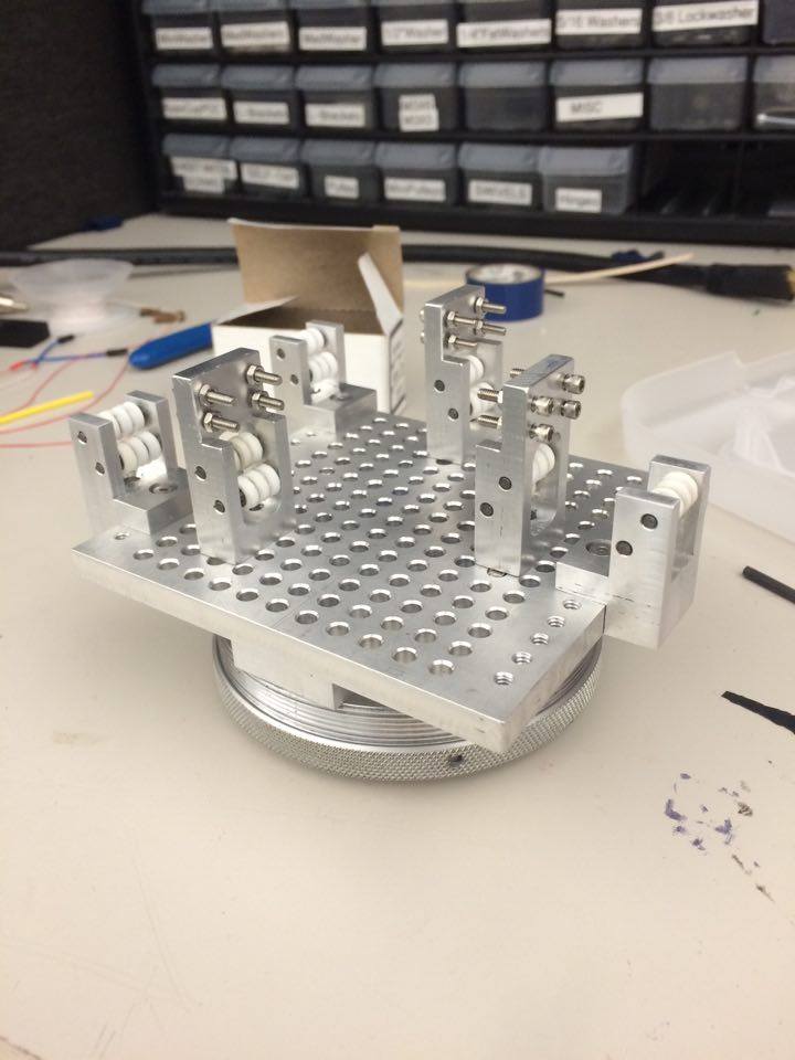
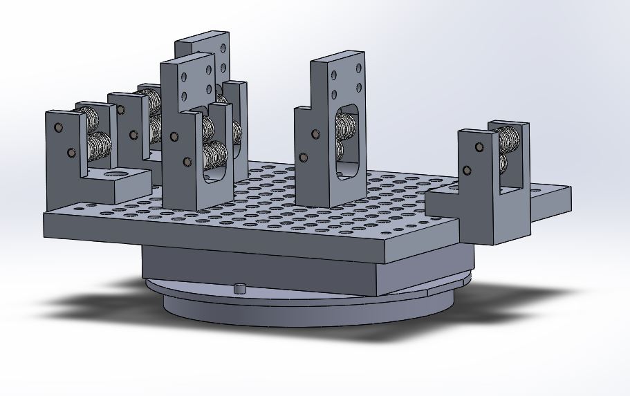
Modular Orientation via T-Slot Frames
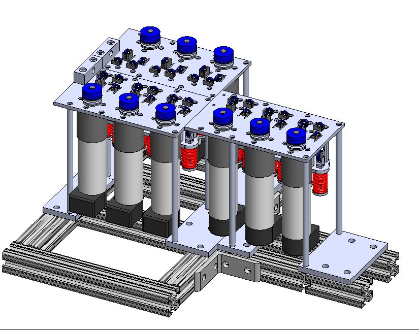
The motor bank could switch between two orientations: the one on the previous page and the one here. This second orientation kept all the vacuum tubes close together, while the first shrank the motor bank footprint.
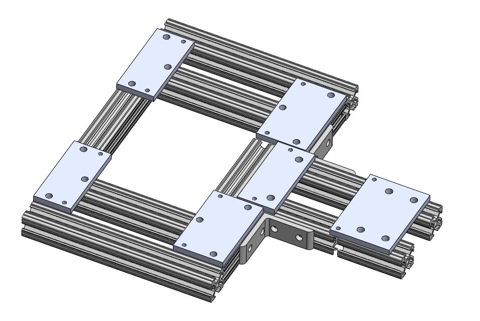
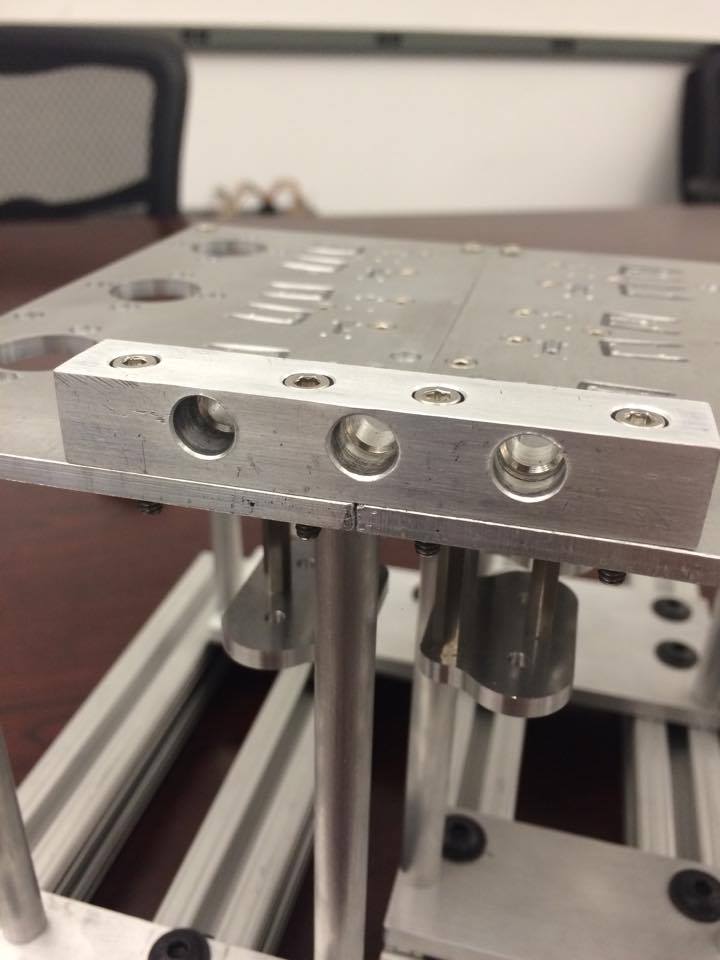
WAM Adapter
Pulleys Redirecting Tendons
The tendons were guided from the edge to the finger holders, through the pocket of the finger holders, and then up into the fingers. It was expected that tension from the motor bank would keep the tendons on their respective pulleys.
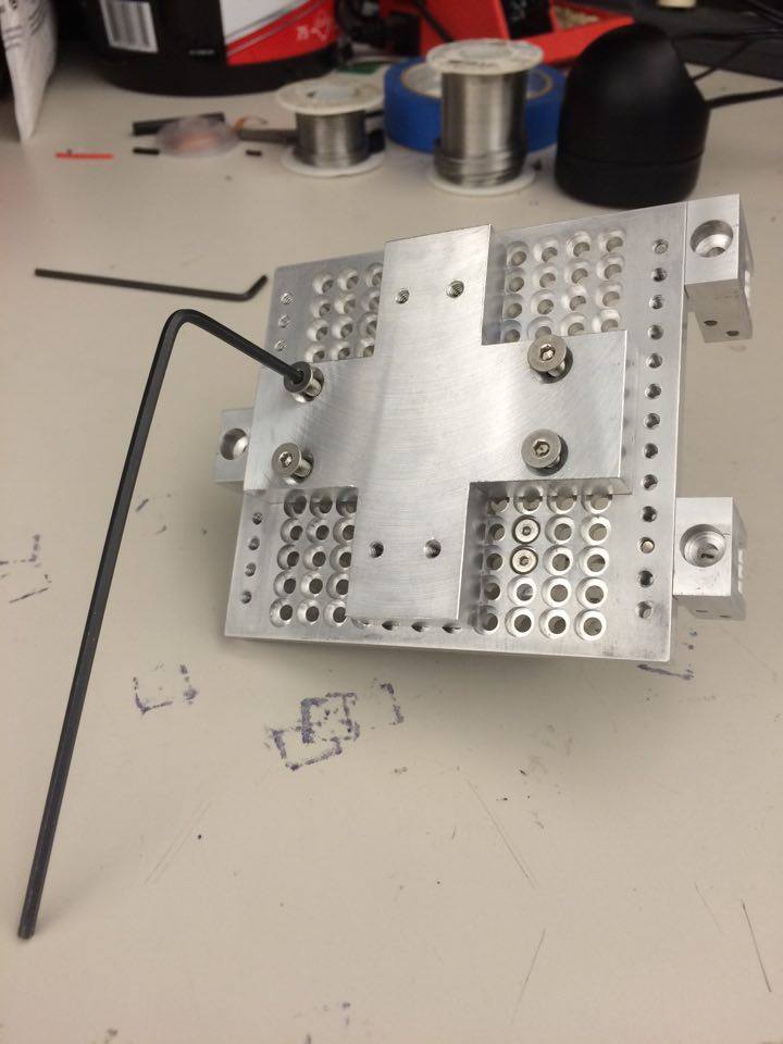
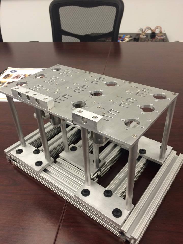
Modular Finger Holder Design
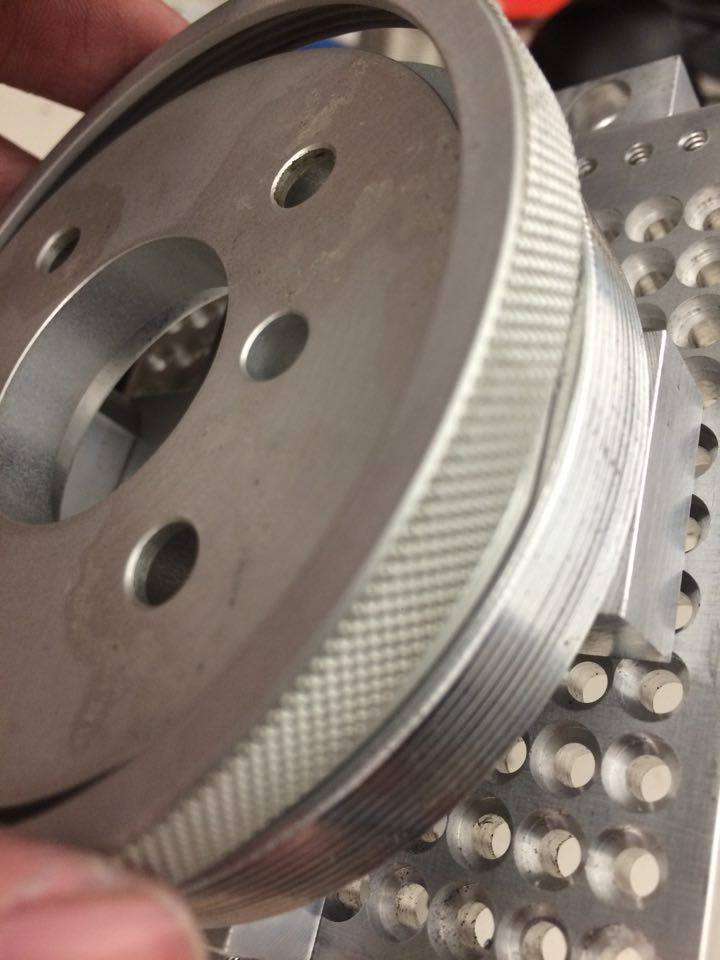
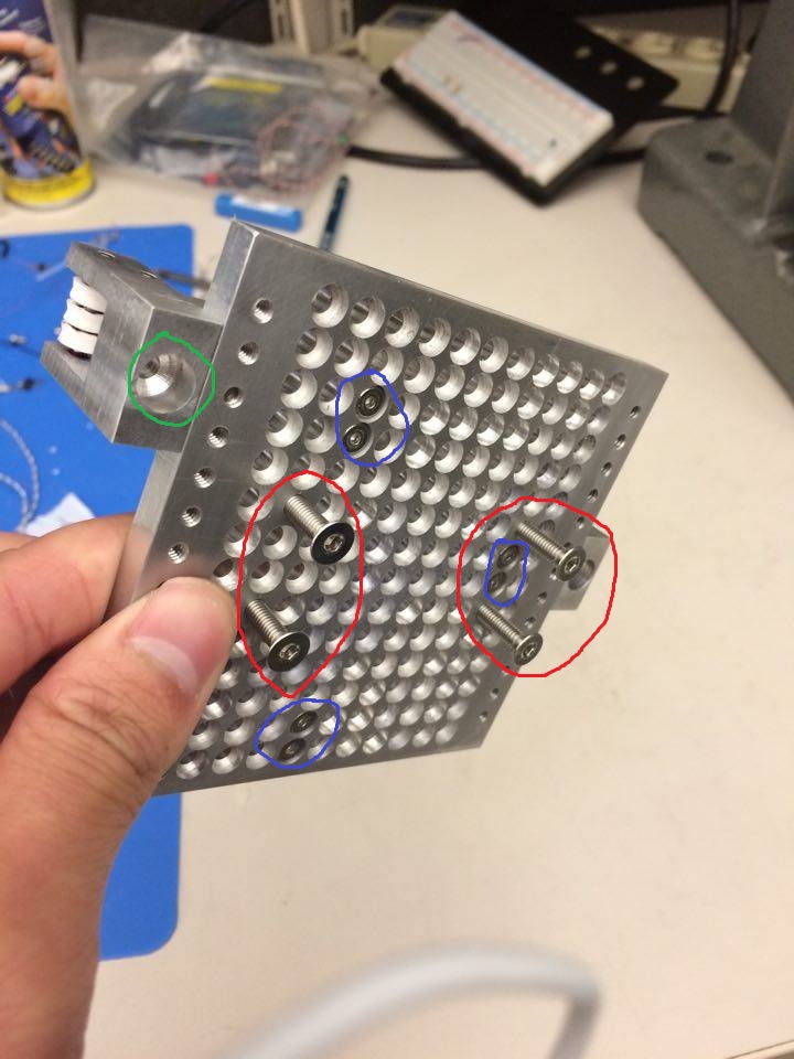
The tendons were guided into the edge pulley holders (circled green) that could translate along the edge of the baseplate to a desired position. The finger holders were screwed into the baseplate (circled blue) at any desired position. Once everything was fastened down, the threaded circular part that linked the baseplate to the WAM was screwed in (circled red).
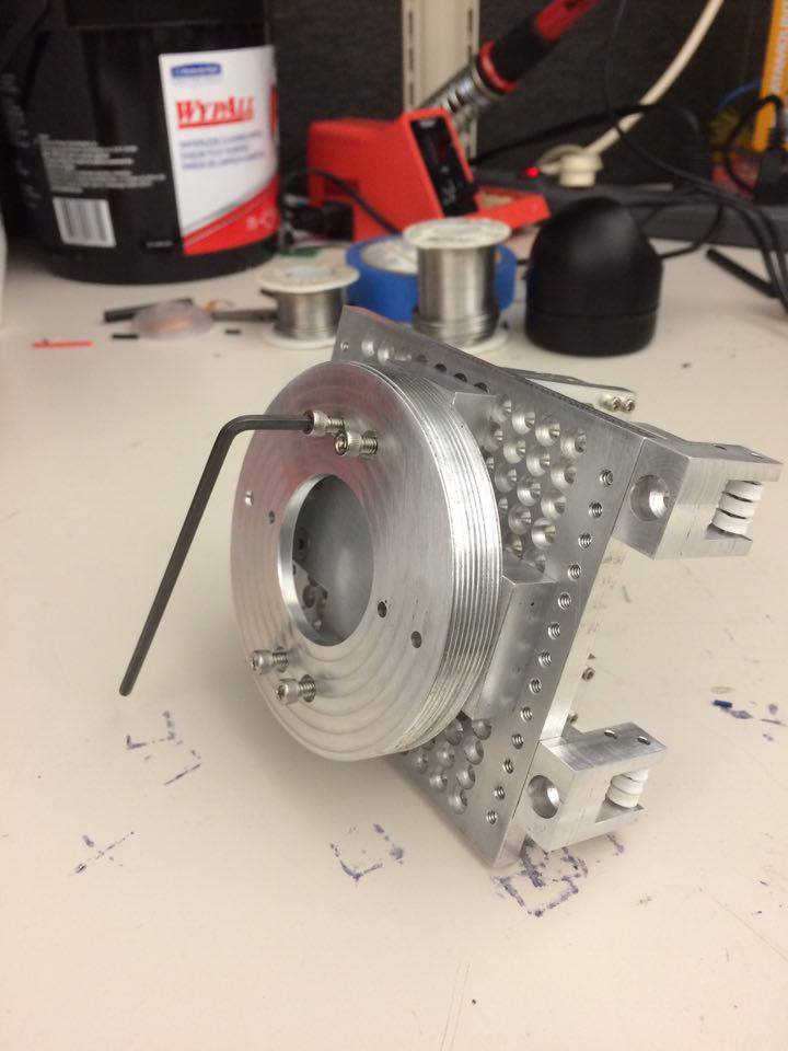
Merging the Bairclaw Fingers to the WAM
The Bairclaw fingers were fastened onto the finger holders via the screws at the top of the part. These finger holders could be fixed over any pair of holes on the baseplate. To attach the adapter to the WAM, a ring clamped onto the WAM wrist as it screwed onto the threads of the WAM adapter at the base (as seen in “Assembly 2” photo).