‘Ninja Warrior’ Sliding Robot
I led this final project when I took 2.740 (Bio-Inspired Robotics) at MIT. Essentially, we were tasked with designing and controlling a robot that exhibits an interesting form of locomotion. For this project, we chose to build a two linkage robot that mimicked this motion we saw on American Ninja Warrior (a parkour competition TV show). Essentially, the person uses their body momentum to slide along a horizontal bar.
Experimental Setup
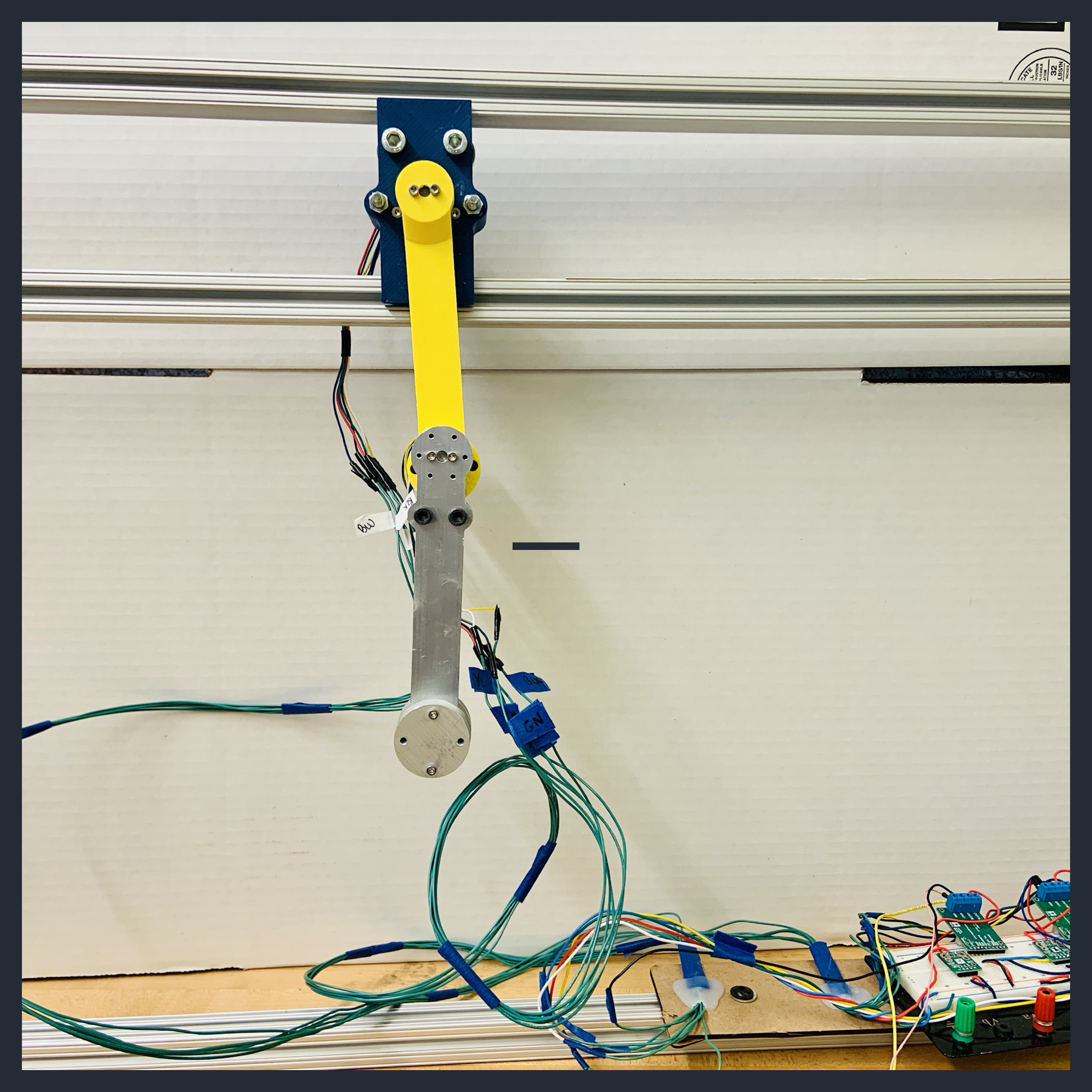
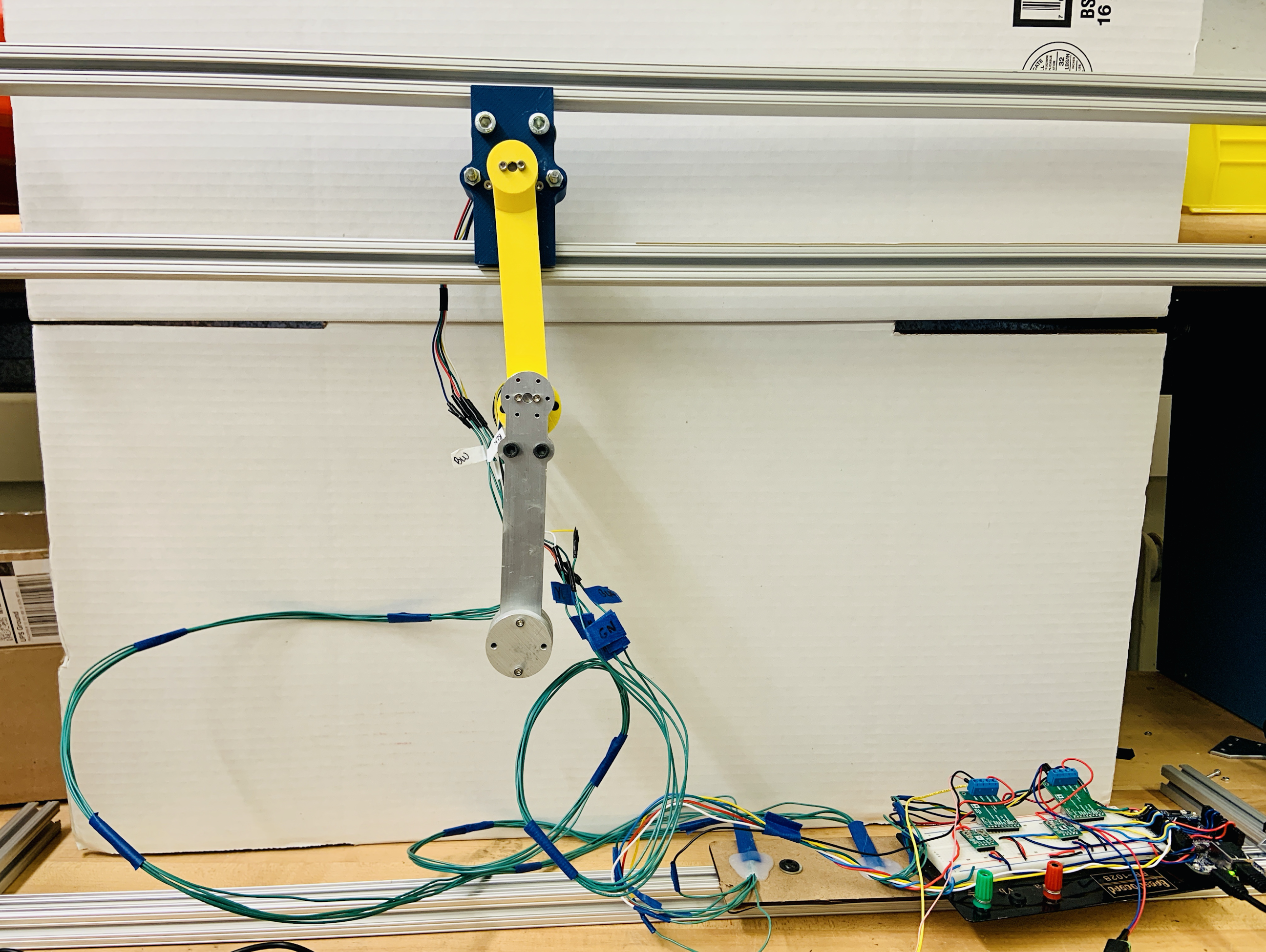
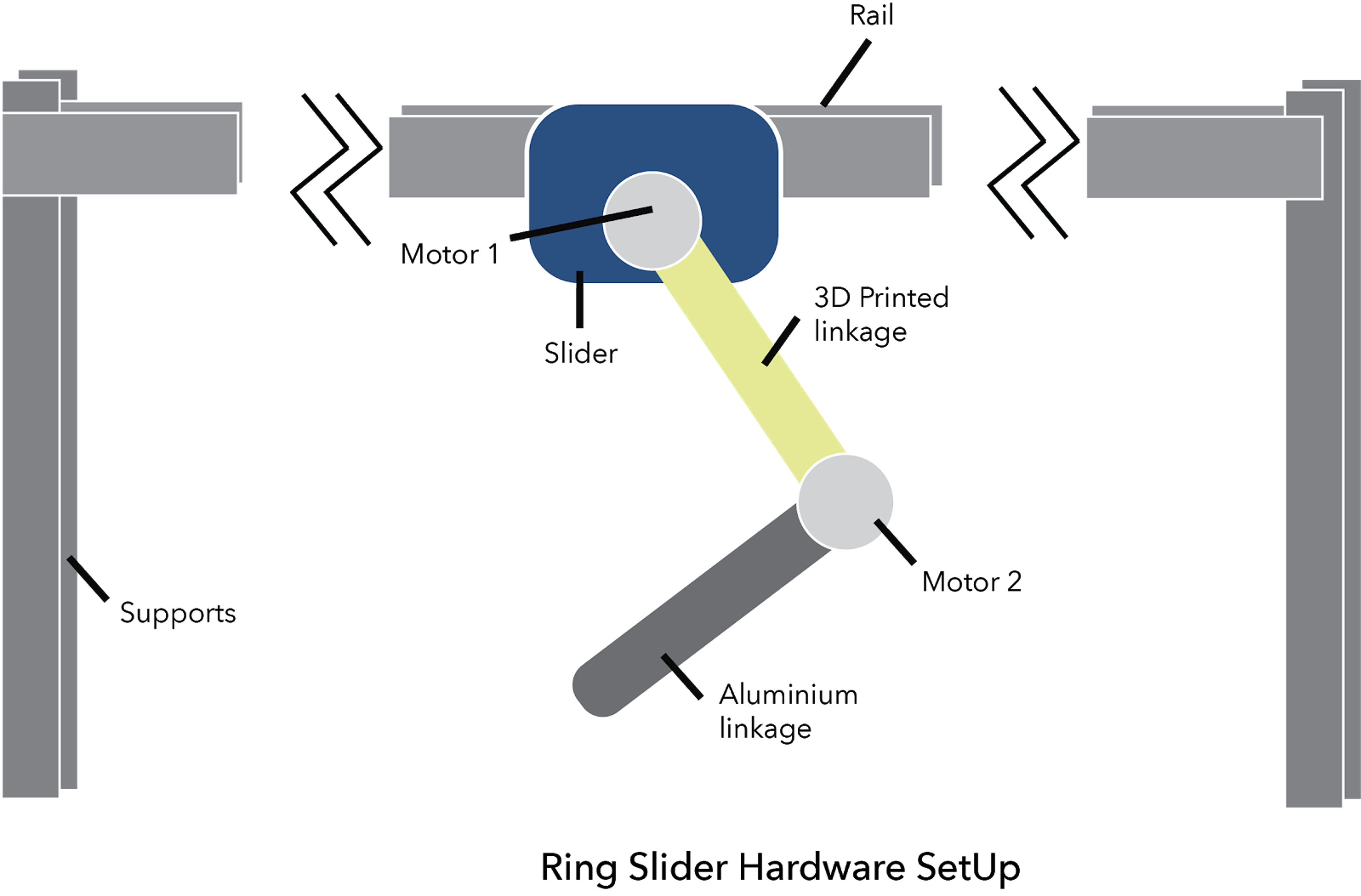
The experimental setup was relatively simple. I designed and built a two bar linkage mounted on a slider that rested between two long T-slot frames. The distance between the two T-slot frames could be adjusted, and for one set of experiments, Teflon material was inserted at the interface between the slider and the frame to create low friction contact. At the end of the second linkage, modular weights could be attached to adjust the center of mass. Each motor on each joint of the linkage was wired up to a microcontroller and current sensor.
Modeling and Simulation
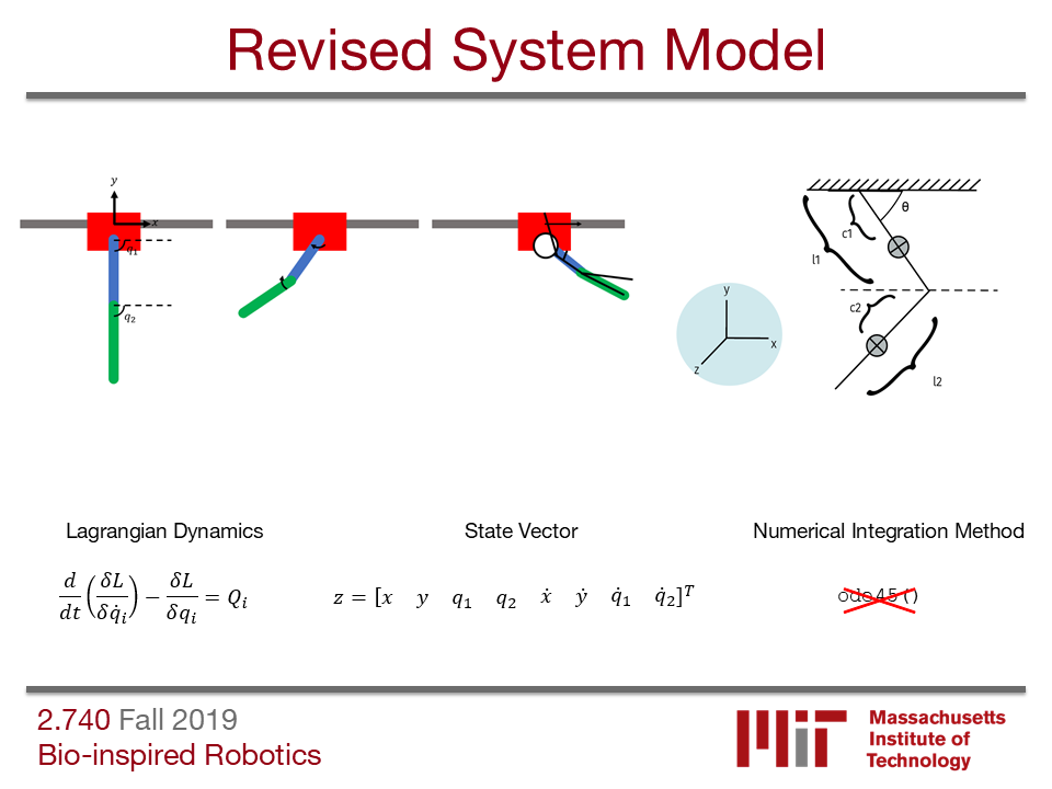
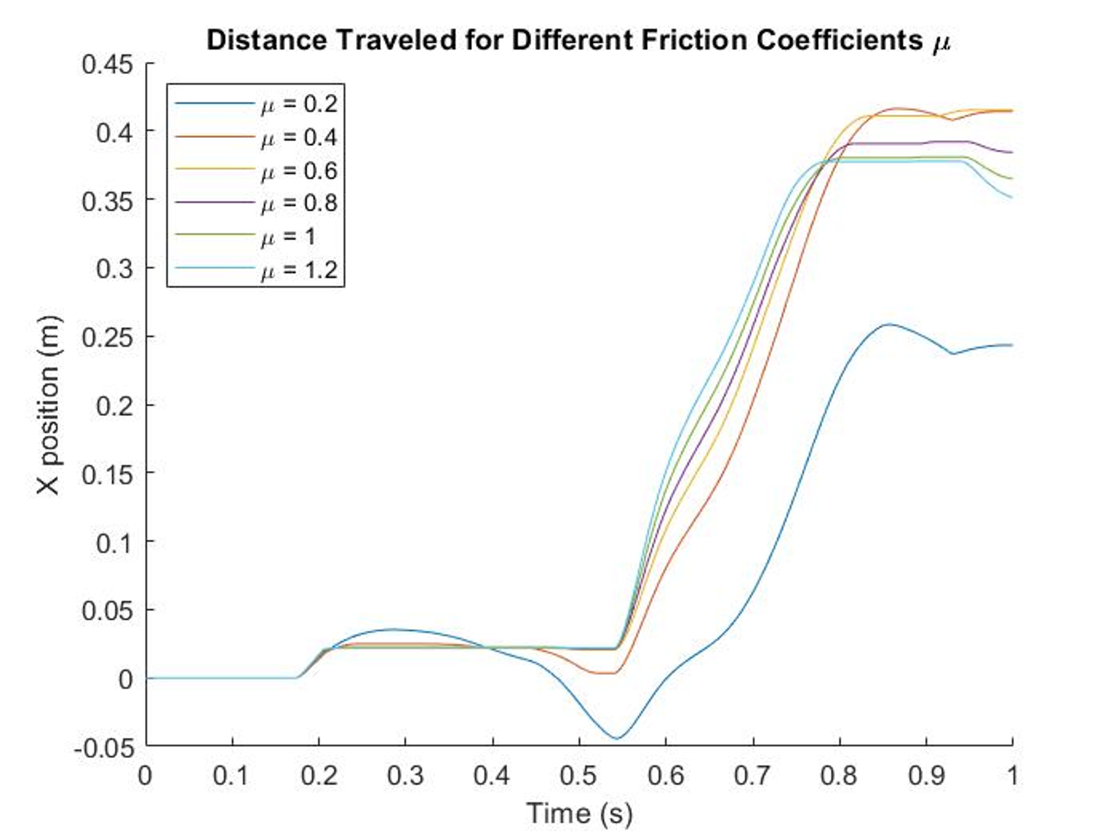
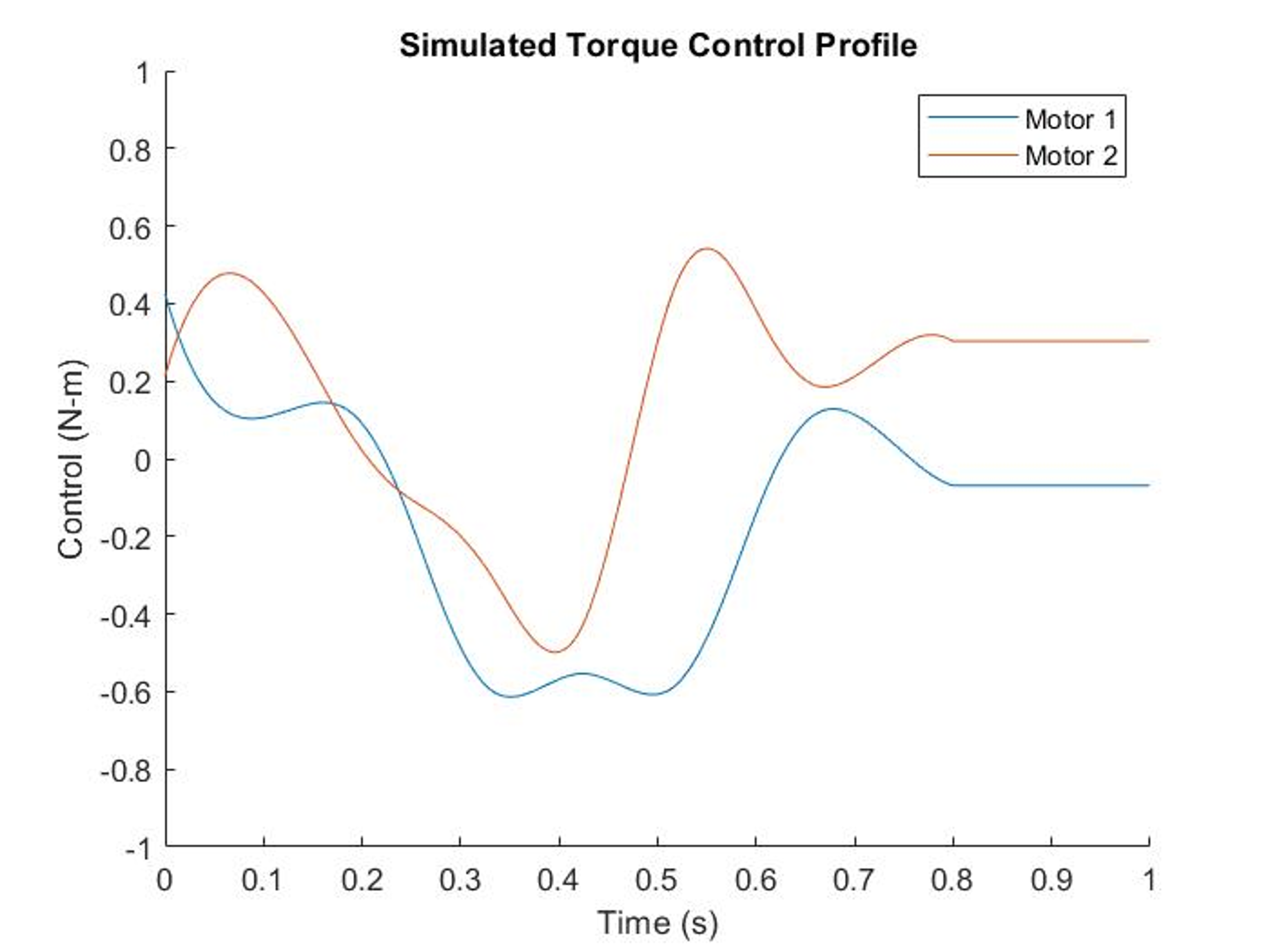
Modeling was done in MATLAB, and the Lagrangian dyanmics were used to find the equations of motion. Simulation was used to find a series of torque commands that would swing the linkages in such a way that the slider would move forward due to the momentum. Below, you can see a simulation of our robot, where the green dot is the center of mass of the linkage.
Control
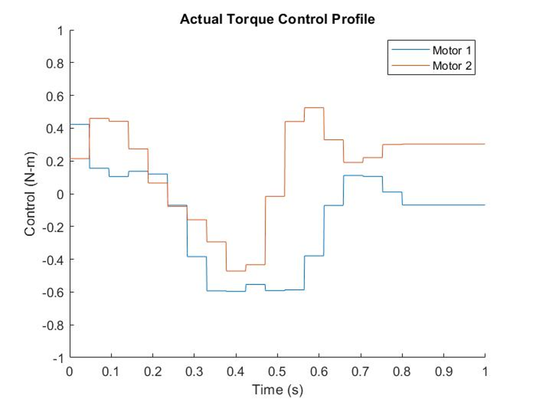
As implied before, the geared DC motors at the joints were torque controlled. Feedback of the current and a PID controller were used along with the provided torque constant of the motor to ensure that the error between the desired torque and actual torque was minimal. For inputting the actual commands to the motor, the torque command control profile was discretized into time steps.
Standard Height Test
The standard height test demonstrated the motion that we were expecting, just not as far as expected. Errors were most likely due to friction as well as a bunch of other factors like slight differences in center of mass and inertia.
Increased Height Test
In attempt to reduce friction, the distance between the two T-slot frames was increased. This allowed the slider to “jump” forward a little more and generate more horizontal travel. However, in doing so, it was observed that upon “landing,” the edge of the slider would contact the frame, and the horizontal movement would effectively stop due to this friction.
Reduced Friction
Another attempt to reduce friction was by sticking some Teflon (low friction material) tap on the slider such that the contact interface between the slider and the T-slot frame had less friction. The distance traveled was a little more than the standard height test, which was to be expected.