Twisted-Winching Hybrid String Actuator
This project stemmed out of a problem I encountered during the development of my climbing robot. Essentially, I had a hook latch mechanism where I needed an actuator with a long initial linear stroke followed by a high force action. One of my labmates (thanks Vineet!) suggested a twisted string actuator (TSA), which seemed perfect. When I was testing my robot, I would tie together the arms with some cord, stick a screw into the cord, and then twist to tighten the arms closer. However, the issue with twisted string actuators is that they tend to have low stroke despite the high force output. Hence came the “brilliant” idea: combining a winch with a twisted string actuator.
We scraped the internet to see if anyone had published or made something like this before. The patent lawyers couldn’t find anything similar during their prior art search. So, we jumped at the opportunity. At the core of our idea is any mechanism that allows a winch to rotate about both its cylindrical and radial axes. Fortunately, I had the mechanism already in use on my climbing robot. From there, we submitted three different papers to conferences and filed the provisional patent in a single semester.
The first paper accepted to ICRA: Download PDF
The second paper accepted to RoboSoft: Download PDF
The third paper accepted to ICCAR: Download PDF
Patent pending: U.S. Patent Application No. 63/694,401
Base Design (ICRA)
Design Description
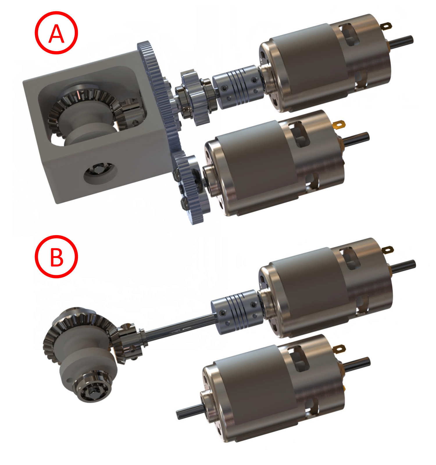
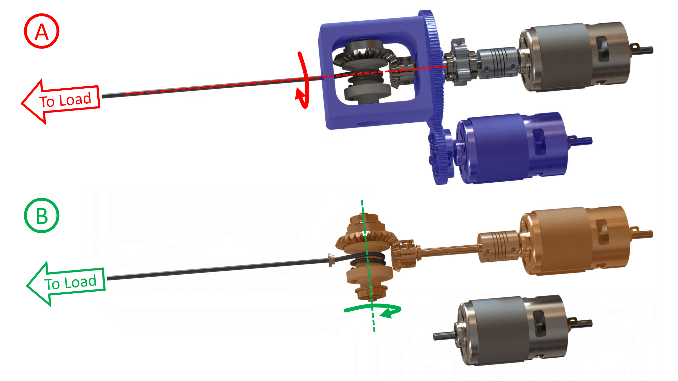
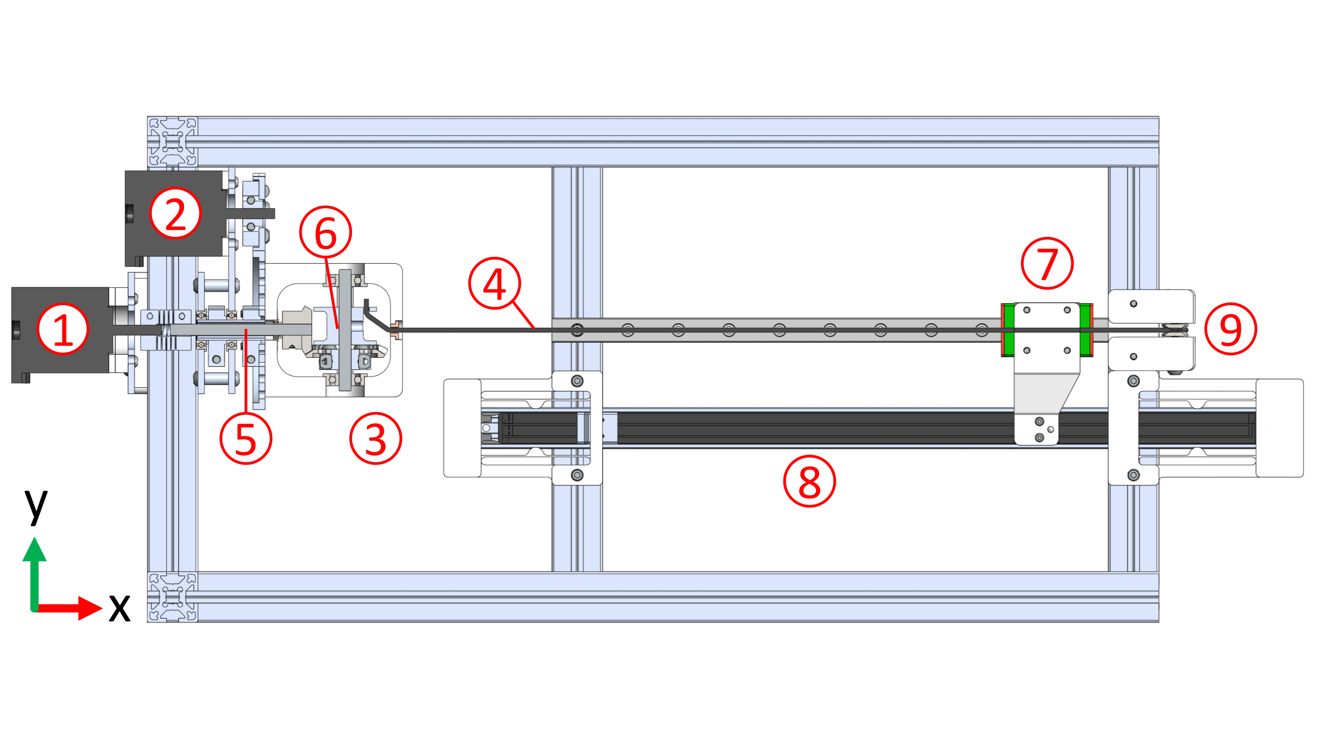
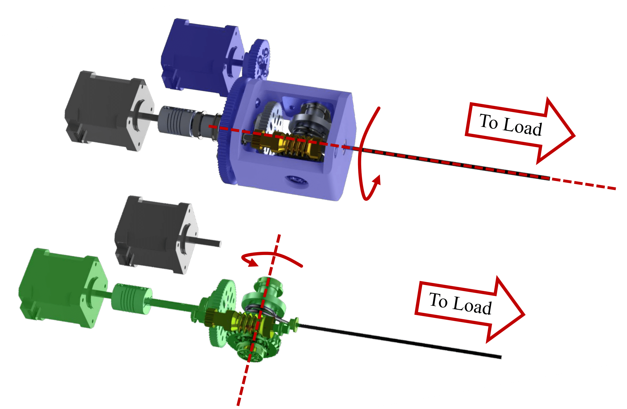
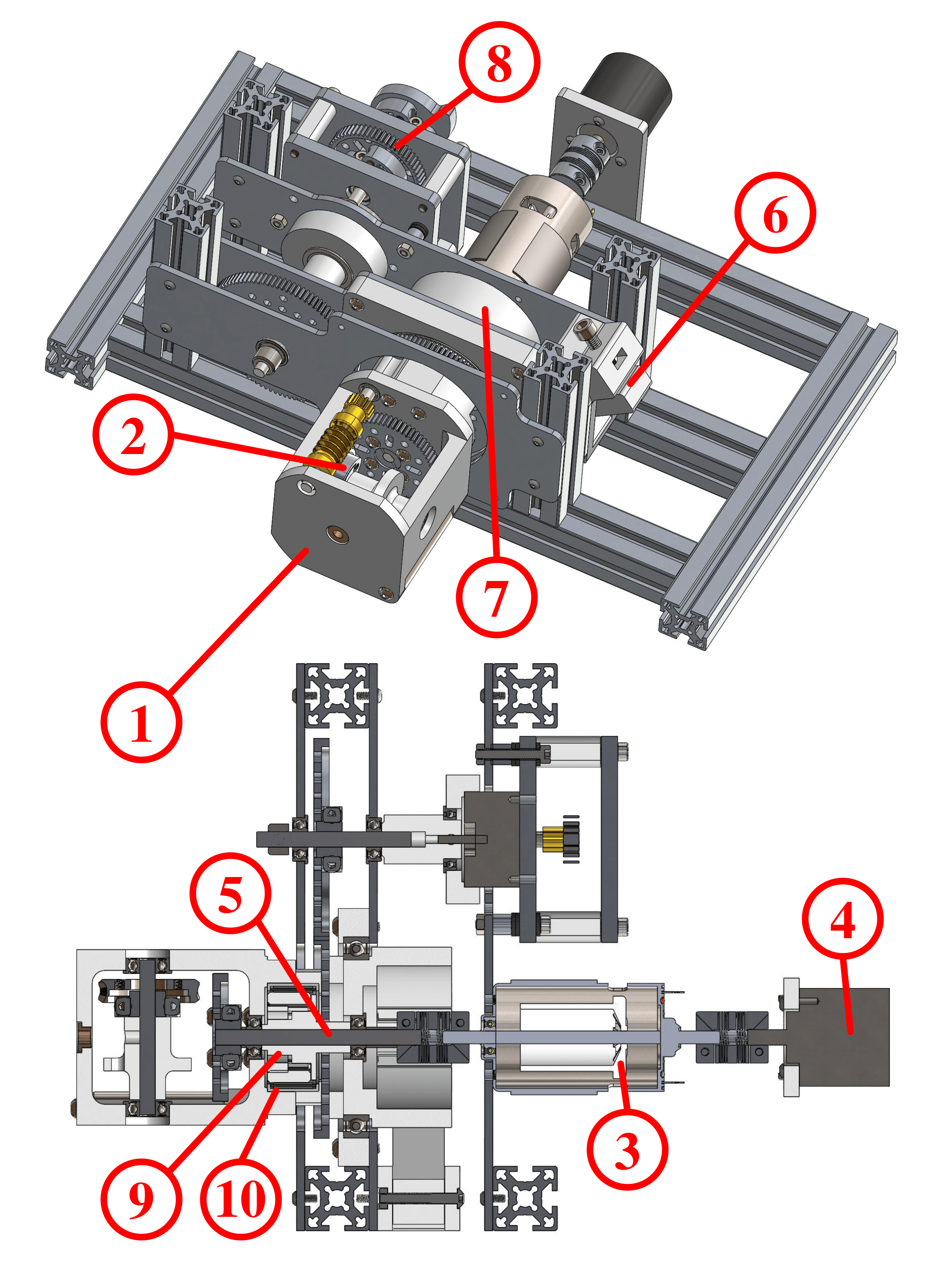
The integrated TSA-winch system provides variable transmission ratios through dynamic adjustment, enhancing actuator stroke and force flexibility for precise, adaptable movement without overtwisting. The performance of this system was evaluated using a rotating turret design that houses a winch mounted on a bevel gear assembly driven by a through-hole drive shaft. Although this design requires one extra motor, the flexibility in motor size and absence of heavy on-axis gearboxes suggest good potential for miniaturization while maintaining large stroke and transmission ratio variability.
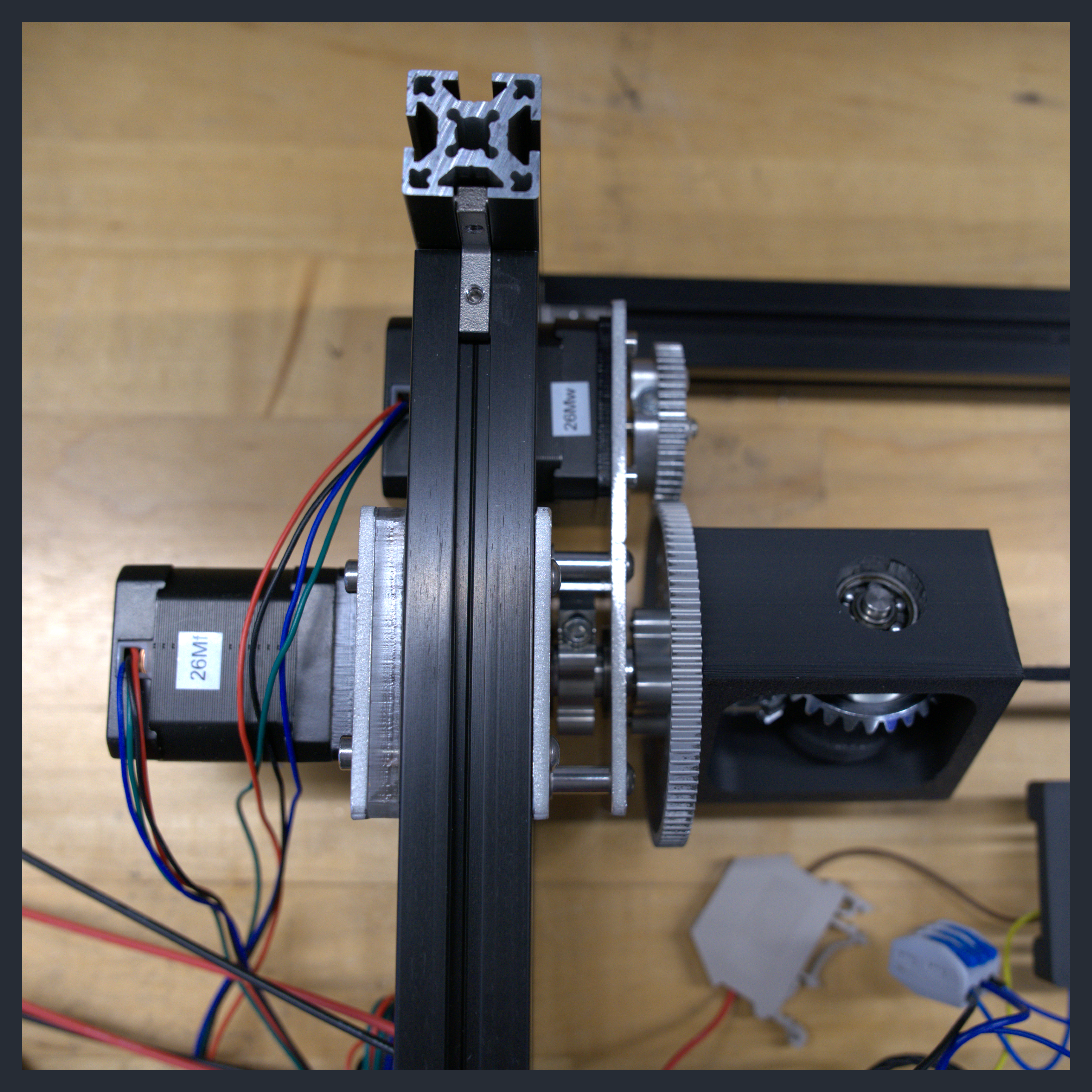
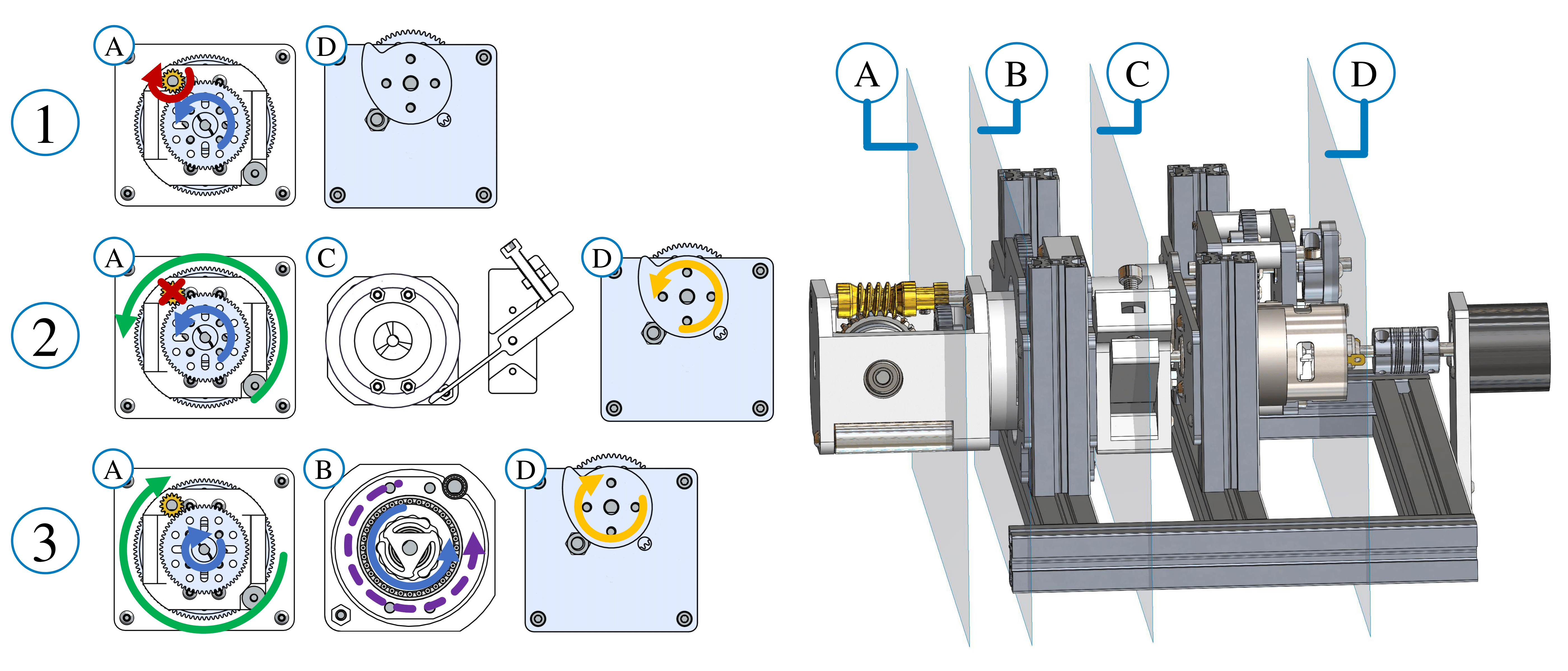
If you look at the pictures below, you can figure out how the mechanism works. For twisting action (highlighted blue), the second motor rotates the turret via a geartrain and thus rotates the winch about its radial axis. For winching action (highlighted orange), the first motor rotates the winch about its cylindrical axis via a bevel or worm gear assembly and a through-hole drive shaft.
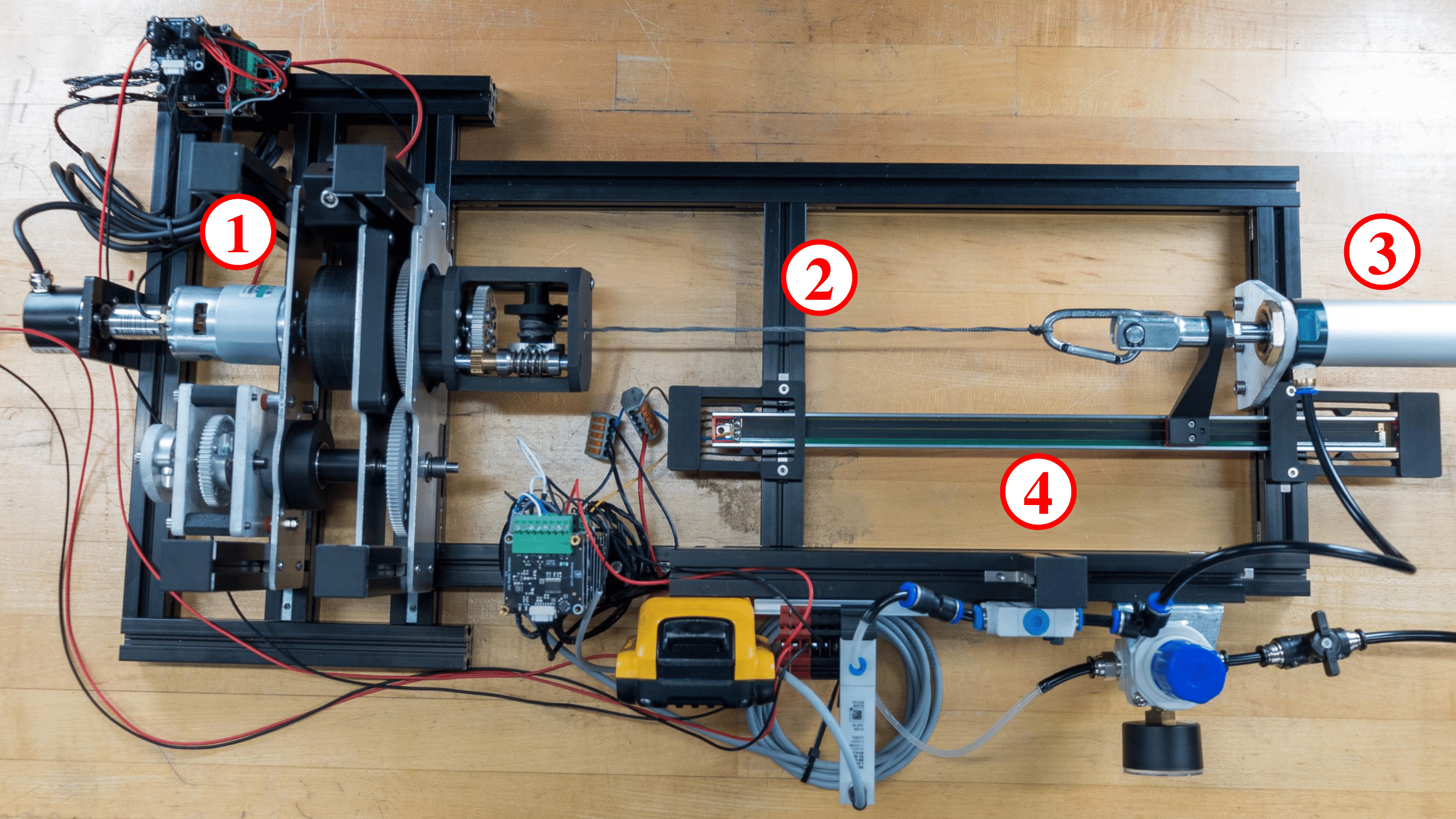
Experimental Setups
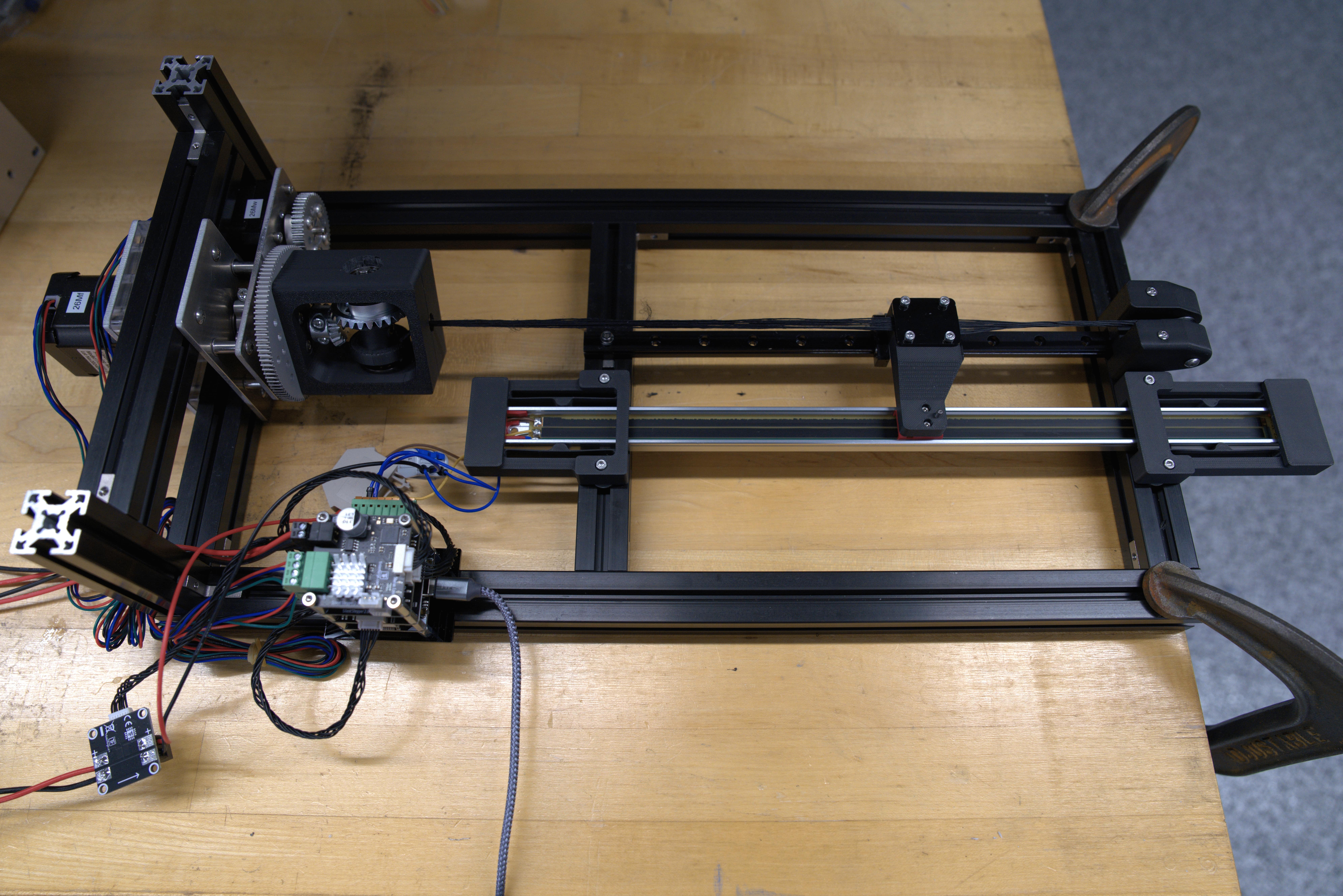
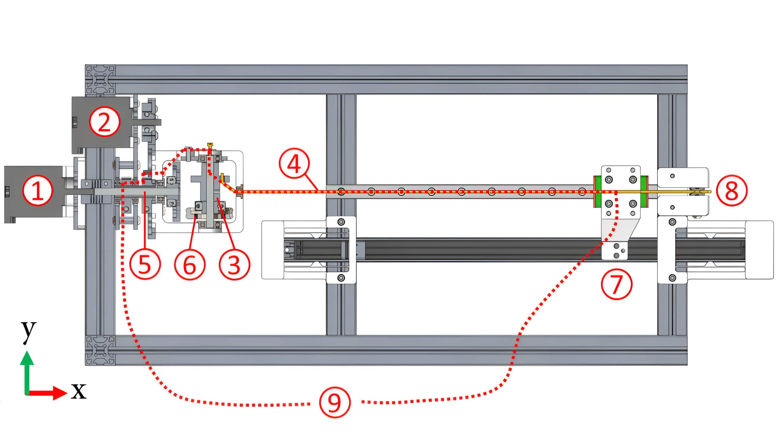
The experimental setup used two motors to manipulatea Dacron polyester bowstring, chosen for its high stiffness and unbraided structure. For displacement measurement, the setup used a linear potentiometer and modular microcontroller hardware developed by TinkerForge. The string exiting the turret was clamped to a linear carriage that slid along a rail when the string was twisted or winched. This carriage was linked to the linear potentiometer that ran parallel to the rail. Because the potentiometer slide lacked bearings and fit loosely in the rail grooves of the potentiometer, flexure mounts constrained it to minimize the binding friction that is common with stages spanning two parallel rigid rails without bearings.
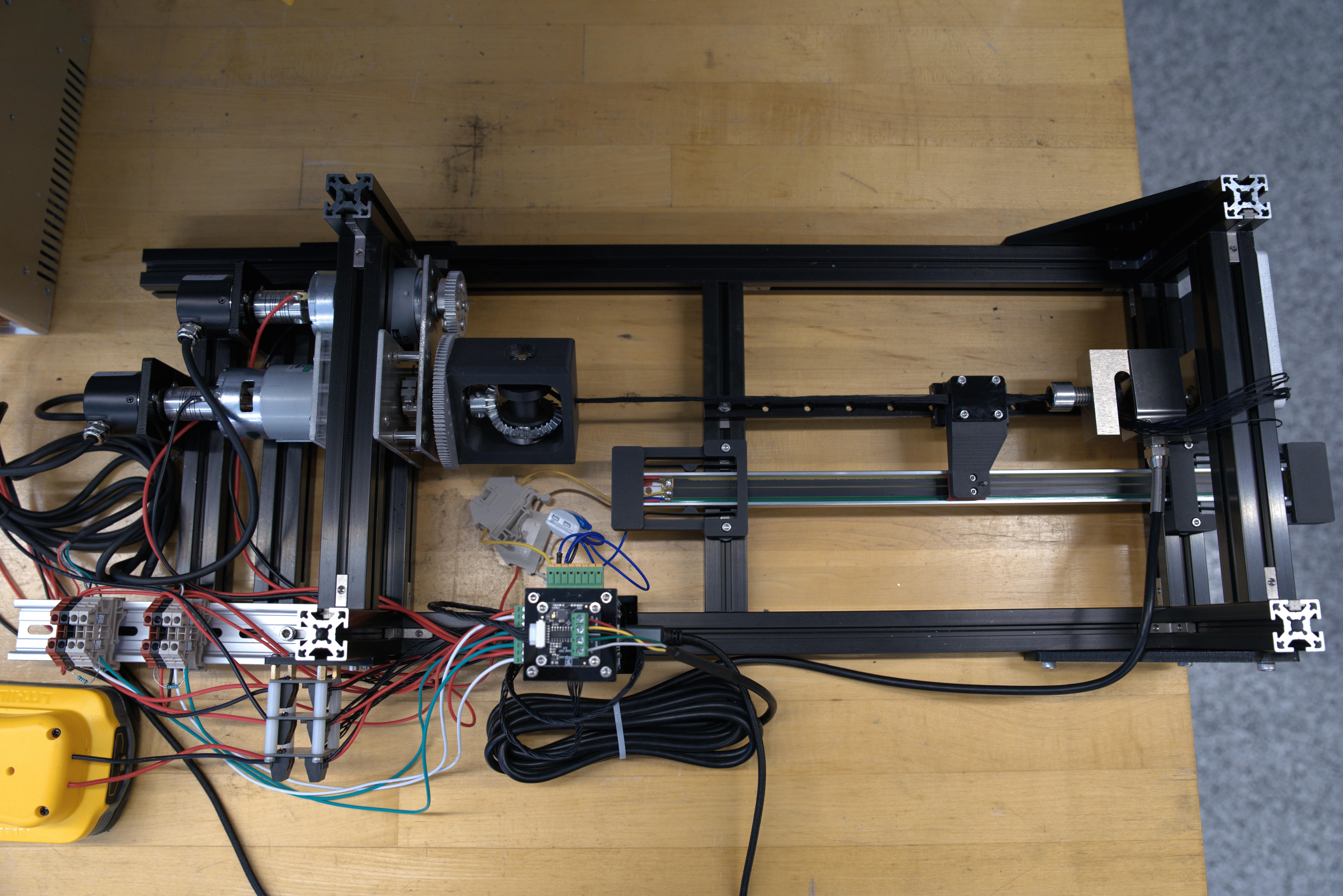
From the clamp on the linear stage, the experimental setup had two forms. To measure displacement, the string passed from the stage to a pulley and then over the table’s edge to a hanging set of masses. Two NEMA 17 stepper motors were chosen for their ease of installation and reliable operation without feedback. For measuring torque input and force output of this actuator, the experimental setup differed. Instead of passing from the stage to hanging masses, the string connected the stage to a PSD-S1 type load cell rated for 100 kg via a vented screw. DC 775 dual shaft brushed motors replaced the stepper motors for more stable current readings. 600 PPR incremental quadrature rotary encoders were mounted on the motors’ backs.
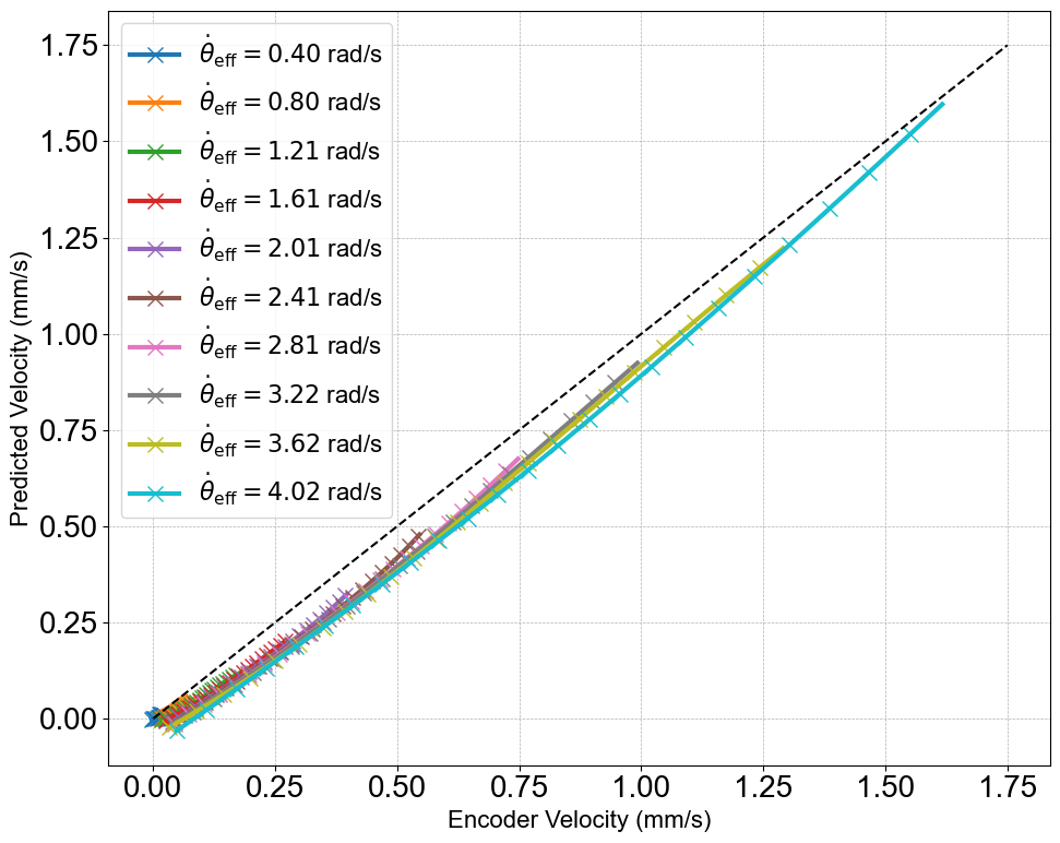
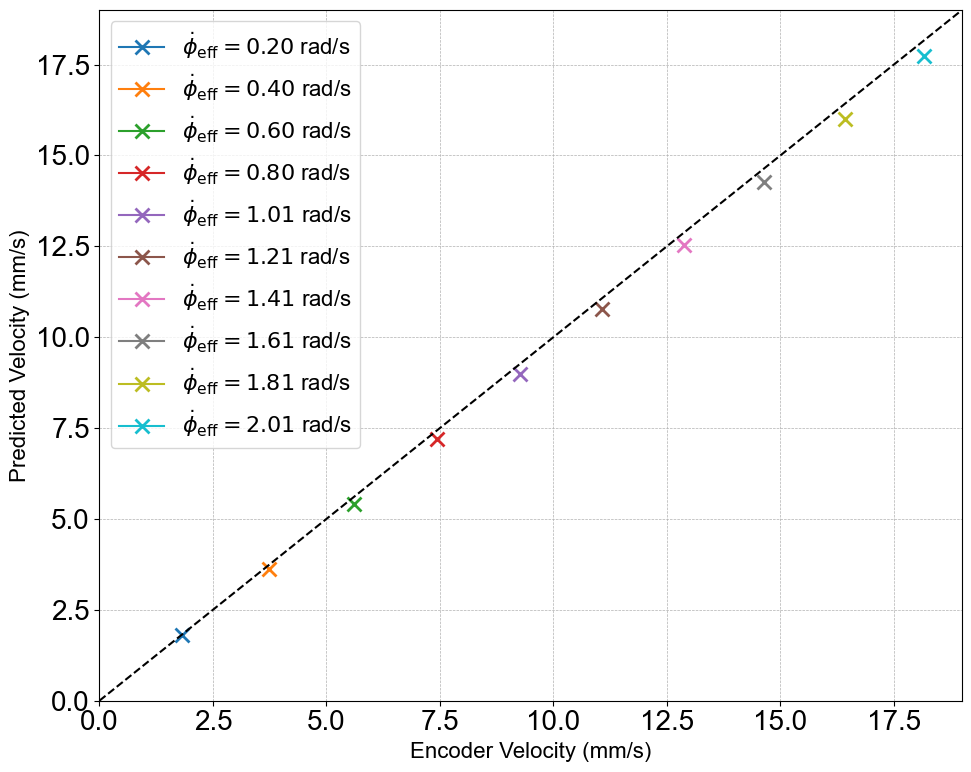
Displacement and Velocity
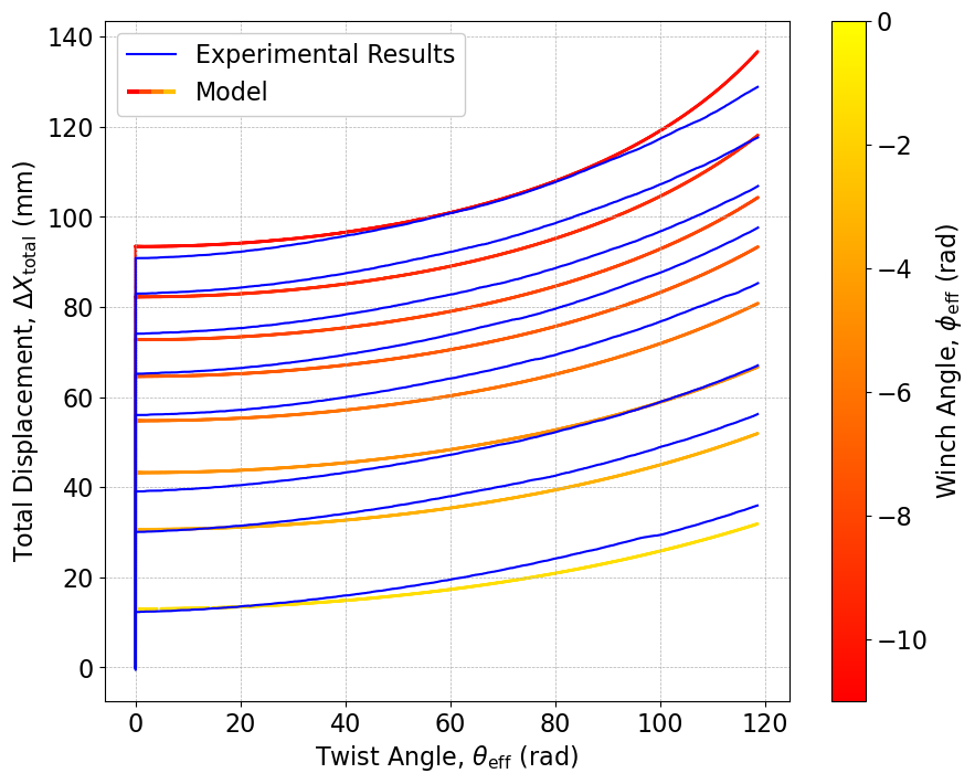
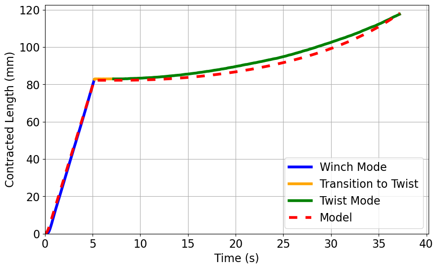
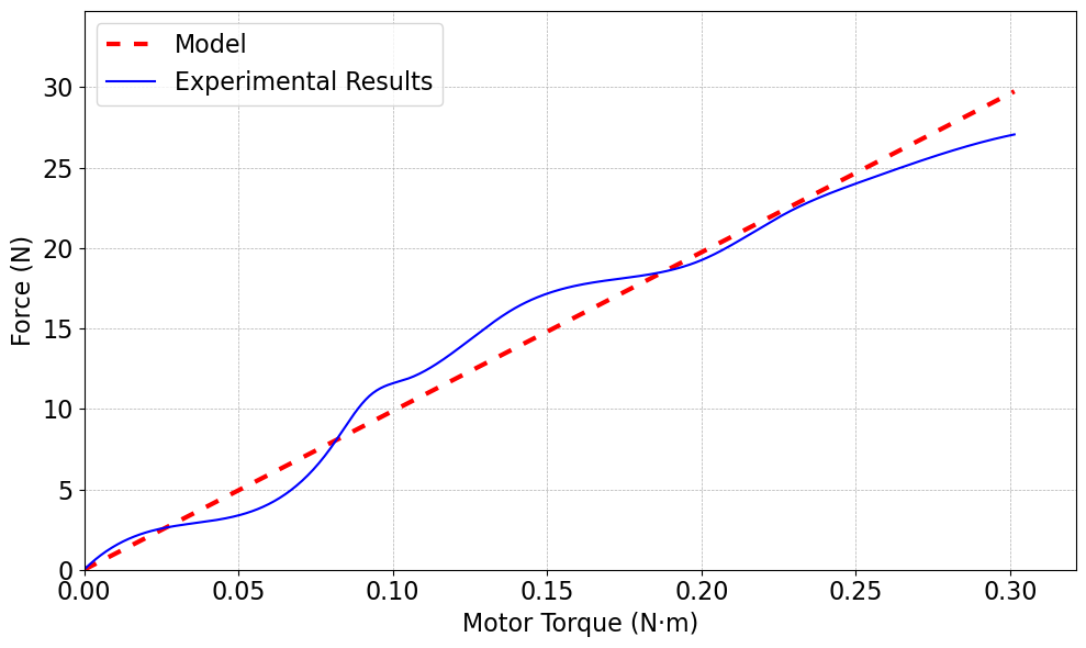
Mathematical models for this actuator can be found in the paper posted at the start of this page. Essentially, these models were based on both standard TSA and winch displacement expressions, taking into account the conservation of volume of the string as it twisted and hence its varying radius. Long story short, the model fit the experimental results pretty well, with errors most likely coming from string stretch, incomplete untwisting before the next cycles, and poor string strand packing.
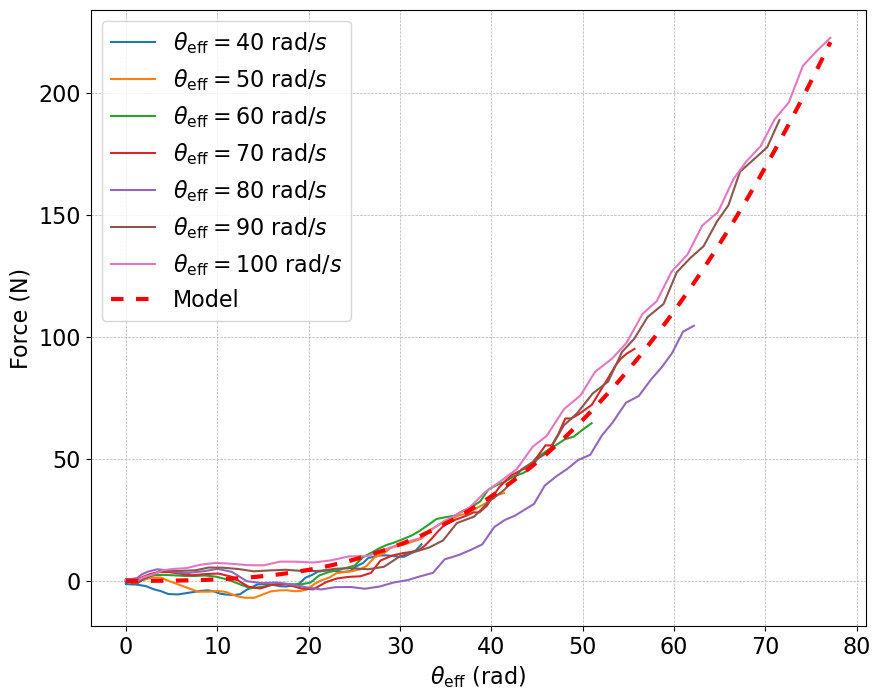
Force Output
Similarly, the experimental force output also matched the mathematical model quite well. As expected, the twist action dominates the force output, while the winch dominates the velocity output. It should be noted that the number of twists was limited in these tests; as I twisted the string more and more at a faster rate, the experimental setup started to collapse on itself.
Feedback Controller (Robosoft)
Redesign of Turret and Gear Transmission
Before developing a controller, a quick redesign was done to swap the bevel gear transmission inside to the housing to a worm gear transmission. This was done because the transmission needed to be non-backdrivable. As the string is twisted, a force is exerted on the winch as well as the object at the end of the string. If the transmission is non-backdrivable, the motor has to exert some torque or else the twisting string will unwind the string already on the winch.
Conductive String
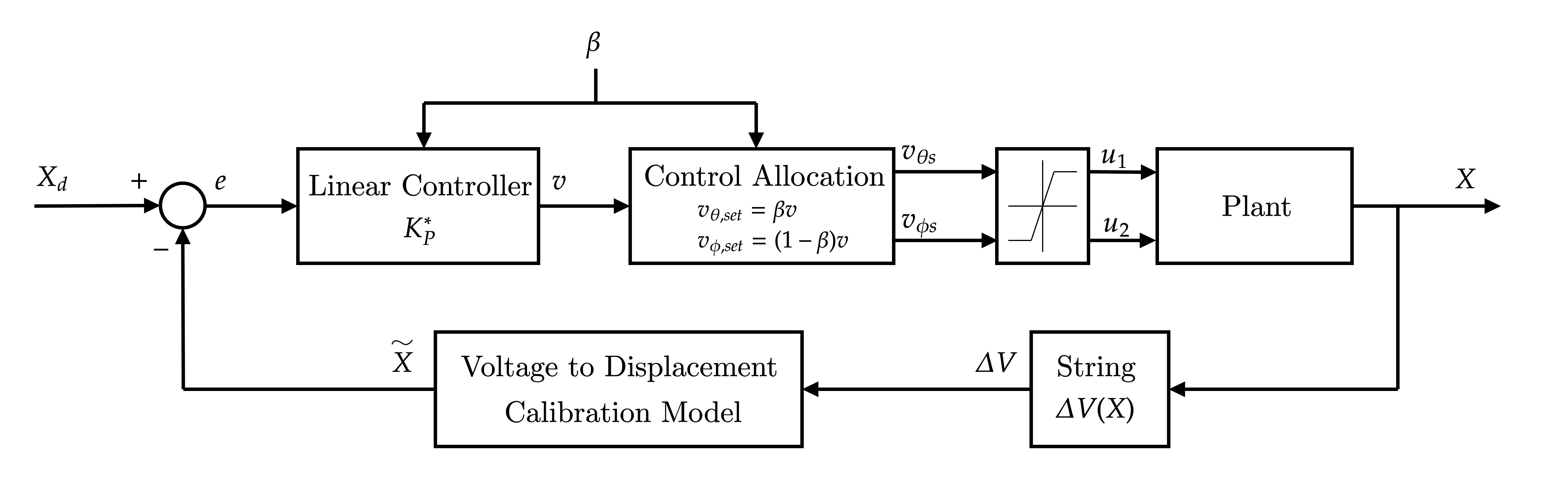
From our first paper, it was clear to see that the open loop control of the actuator wouldn’t suffice for precision operation. While a standard encoder at the end of the string would work just fine for a feedback controller, we wanted to explore the use of a conductive string as feedback. By measuring the change in resistance as the string was twisted or wound up, we could get a pretty accurate position estimation from a model relating the resistance to displacement.
PID Controller and Gain Scheduler
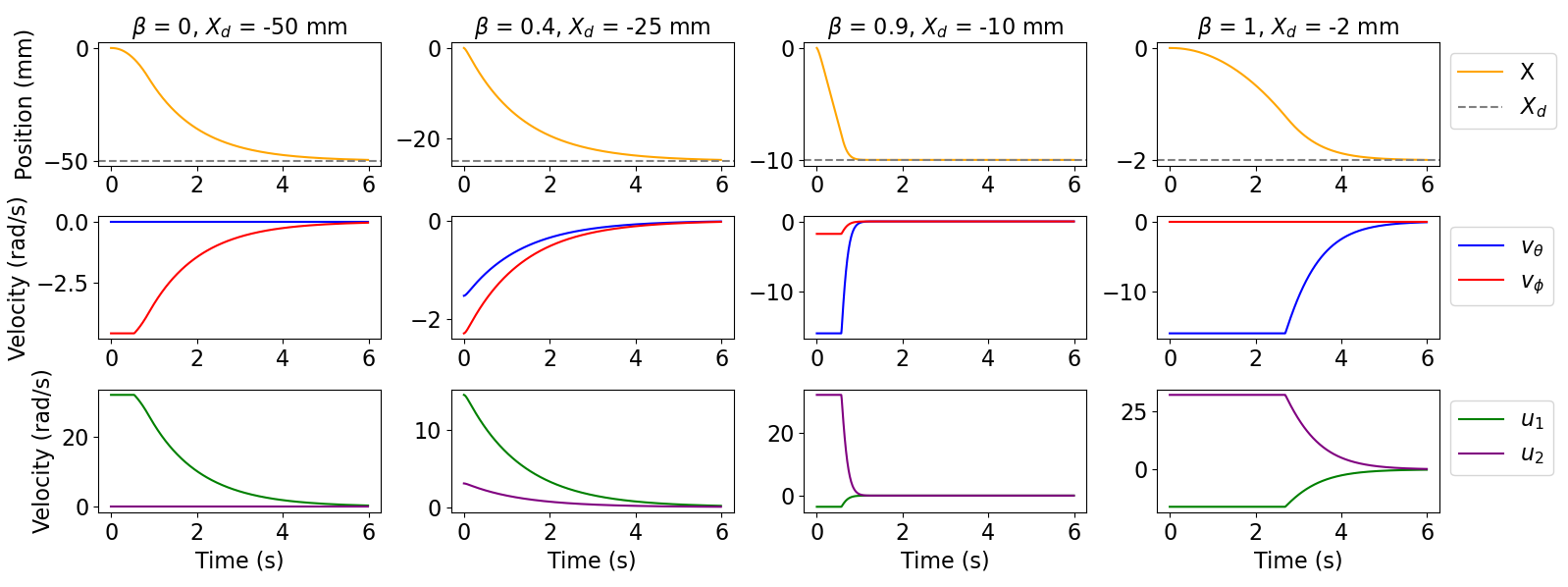
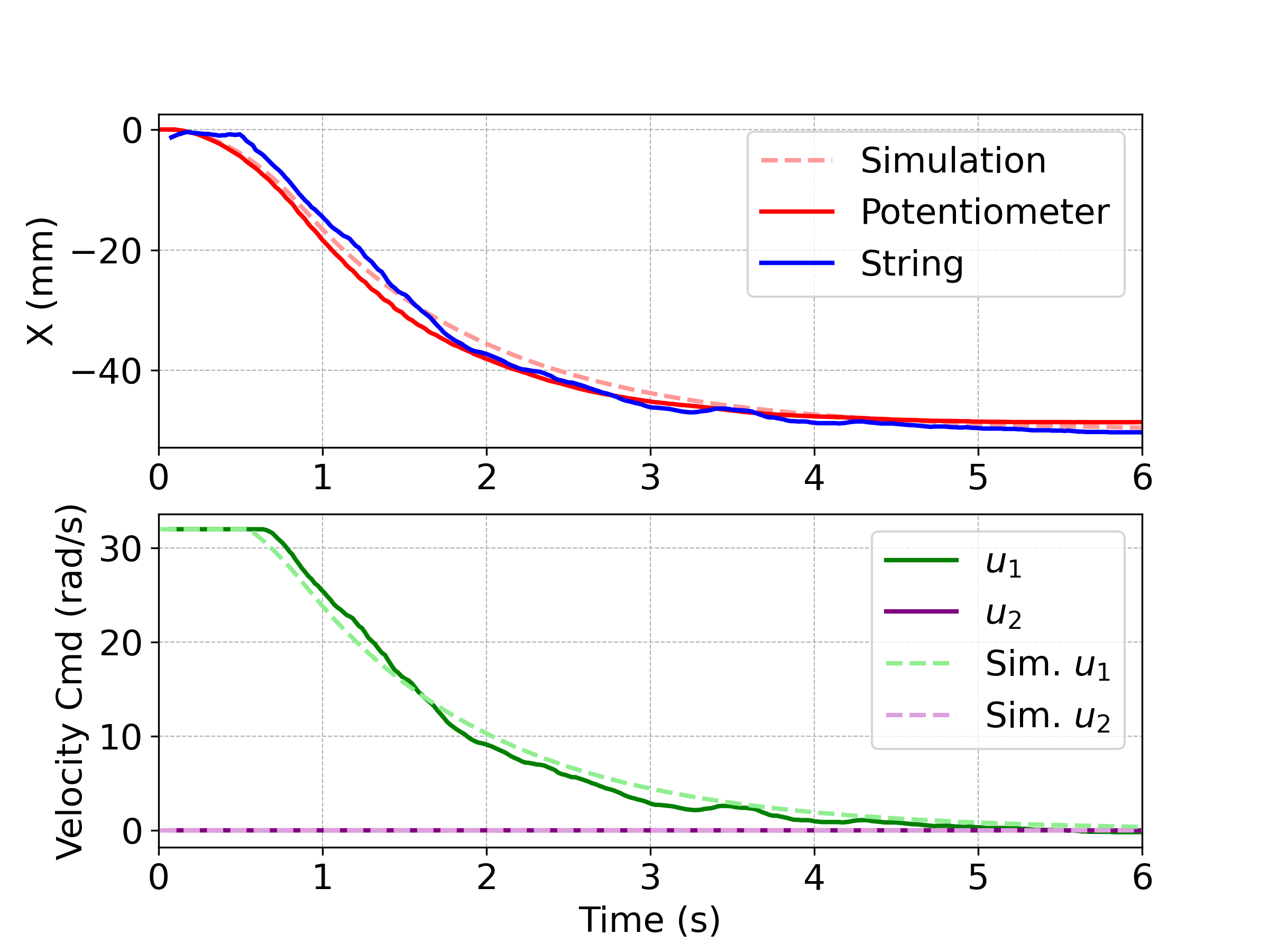
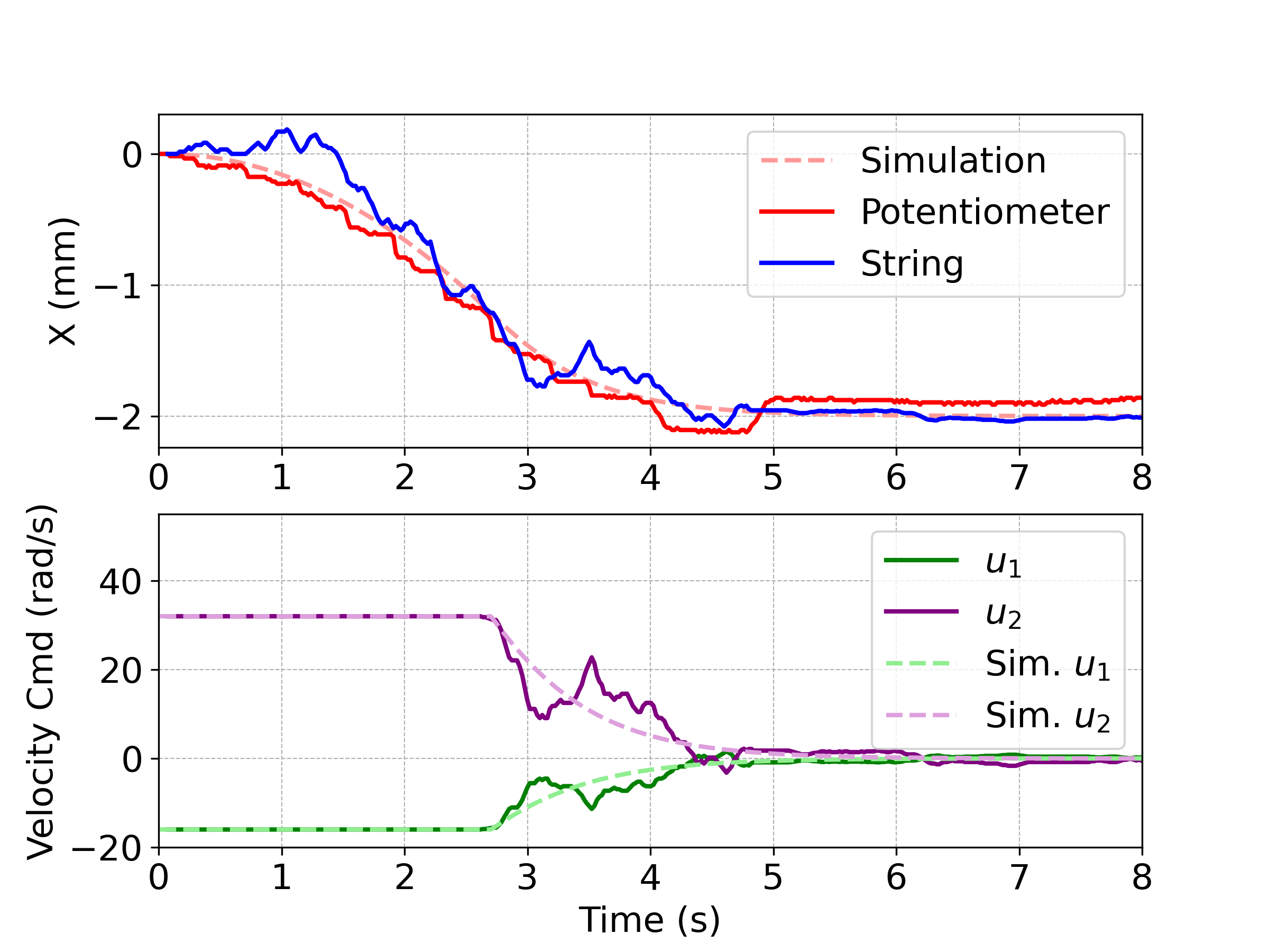
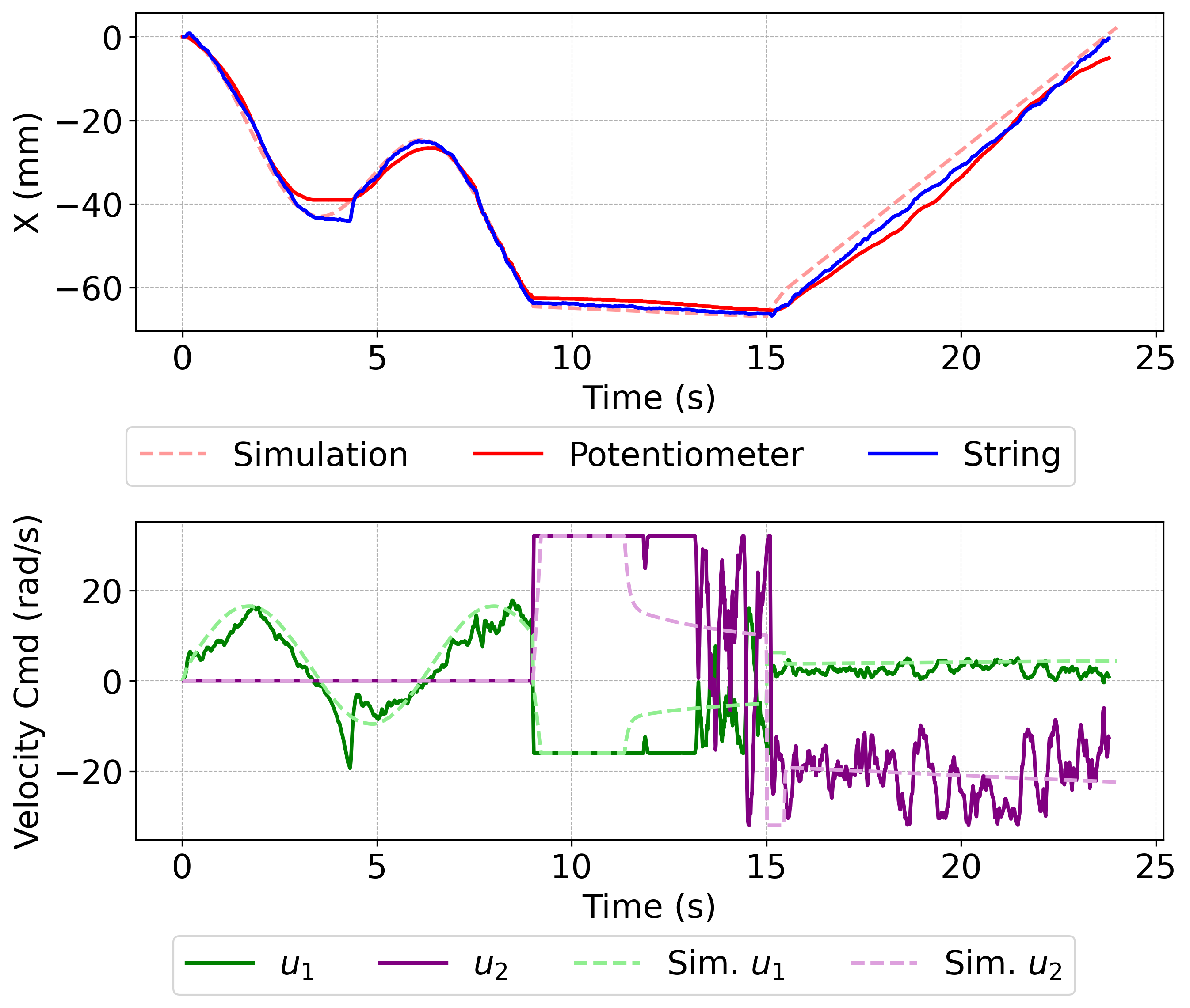
For the second paper that was submitted to Robosoft, a feedback controller using a gain scheduling scheme was used to control the position of the string. The string was made to be conductive; by measuring the change in voltage as the string was twisted or winched, the displacement of the string could be measured. The controller depended on a control allocation factor beta, which was a user-defined value between 0 and 1 that proportionally allocated control effort between the winching and twisting actions. The closer the value of beta was to zero, the more winching action was done.
Single Motor Design (ICCAR)
The Motivation
One thing we always wanted to do during the course of developing this actuator was to replace one of the motors with a mechanism to simplify the control. In doing so, we would sacrifice the ability to control the twist and displacement state of the string, so the actuator would be ideally used in cases where a large displacement was needed followed by high force twisting action. This transition would be facilitated by a sort of friction clutch that triggers when the load at the end of the string goes beyond a certain threshold. It should be noted that we didn’t enforce physical space as a constraint on the design and the experimental setup. However, this actuator can be greatly miniaturized, as all of the components can be made quite small.
The Mechanism
Unfortunately, this mechanism is very hard to explain without a CAD model. It merges the advantages of winching and twisting into a single-motor driven unit. An automatic friction clutch, inspired by planetary gearbox mechanics and triggered by a high end-effector load, allows the actuator to transition from winching to twisting, maximizing force output according to the user’s desired number of rotations. This number of rotations is mechanically stored using a dial on the output shaft of a high-reduction gearbox. Furthermore, a slip clutch integrated with a unidirectional bearing enables complete untwisting and unwinching, ensuring the actuator can reliably return to its starting configuration. For full comprehension of the design, it might be best to read the paper we wrote and submitted to ICCAR.
Experimental Setup
The experimental setup was a little more complicated here because we wanted to provide varying loads to the end of the string and see when the transition from winching to twisting was triggered. To do so, we used a pneumatic piston and various valves to control the amount of load that the string experienced.