‘Wedgie’ Flagship Battlebot
My second 60-lb flagship battlebot, nicknamed “Wedgie”, was a robot I completed in my third year as the project lead of the flagship team. With many members of the previous year’s team graduating, I directed the development of the battlebot, managed team dynamics, organized the budget and purchases, and was heavily involved in Wedgie’s design and manufacturing.
“Wedgie” went on to make it to the third round of the lightweight division at the 2018 Robogames competition.
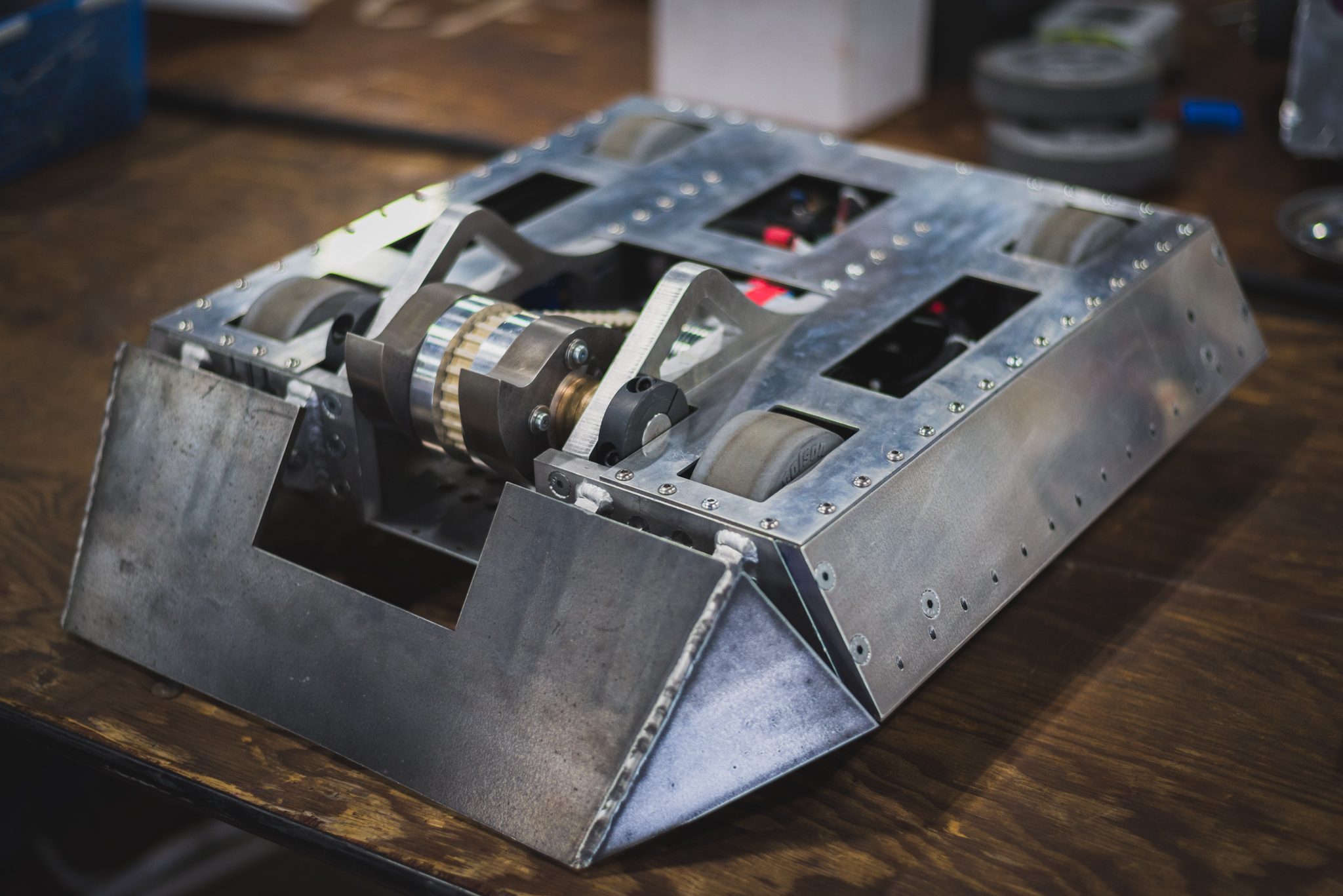
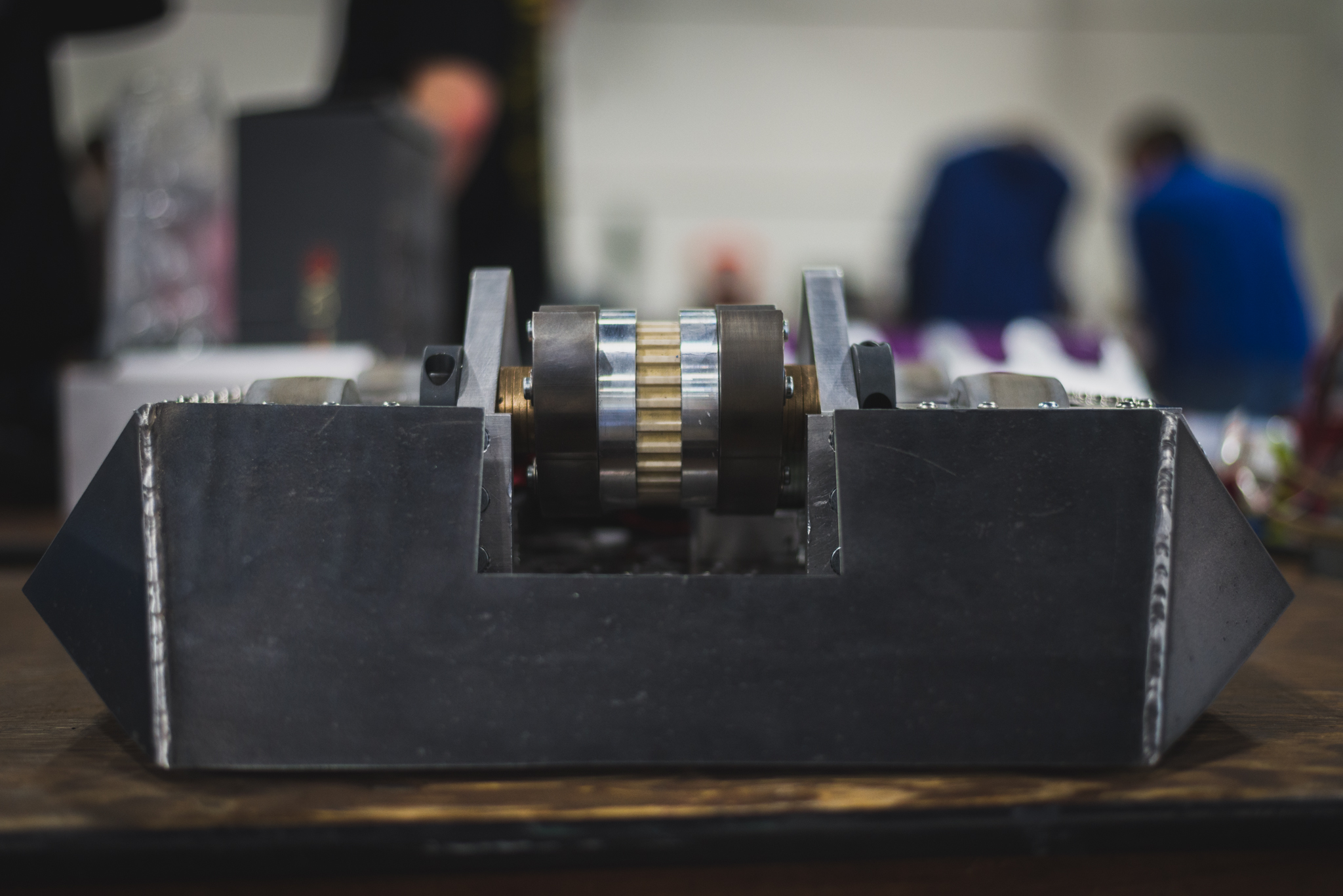
Wedge and Vertical Spinner Weapon
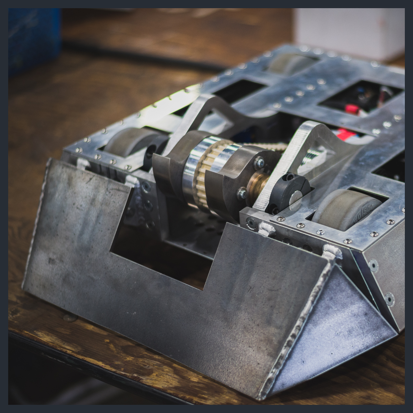
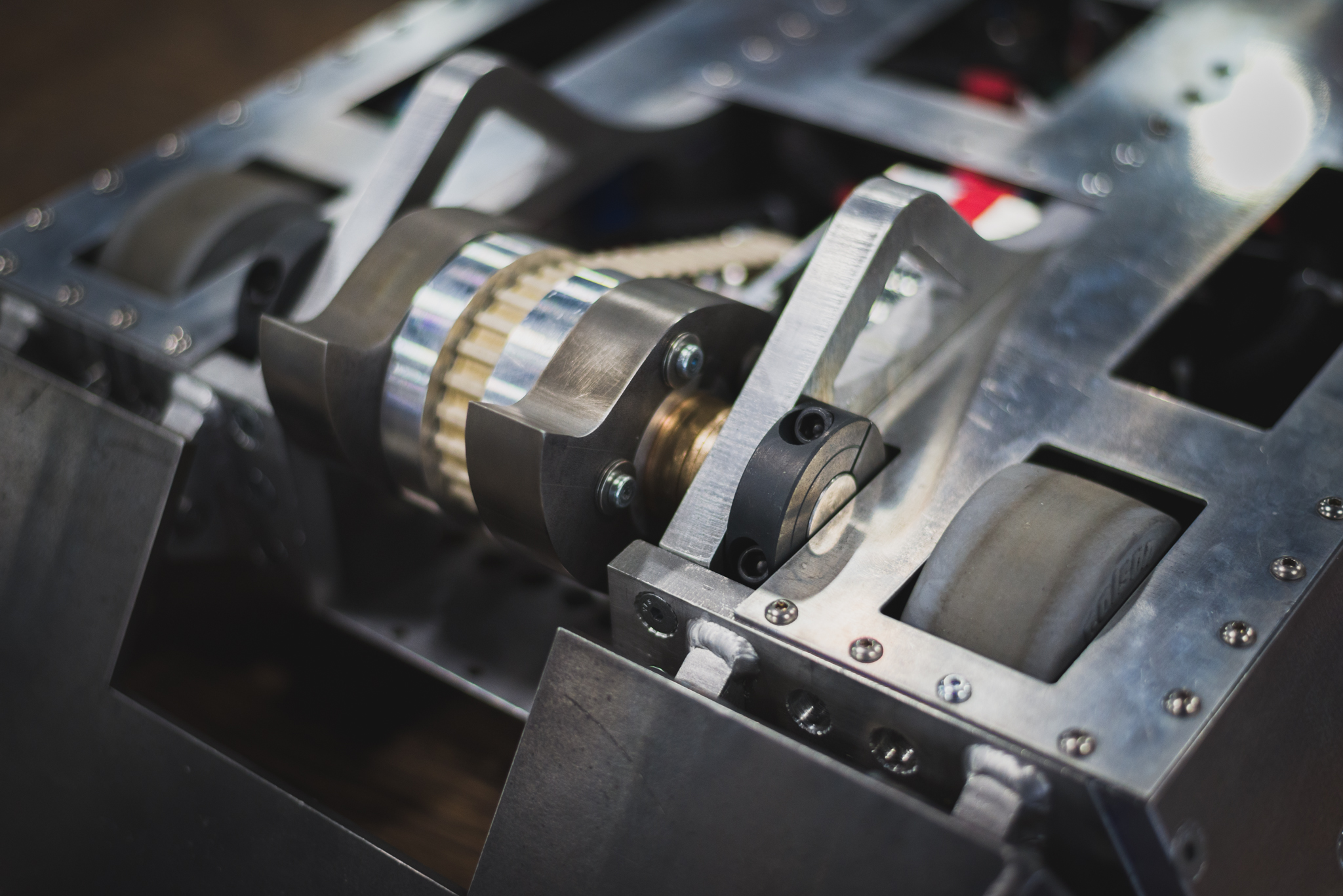
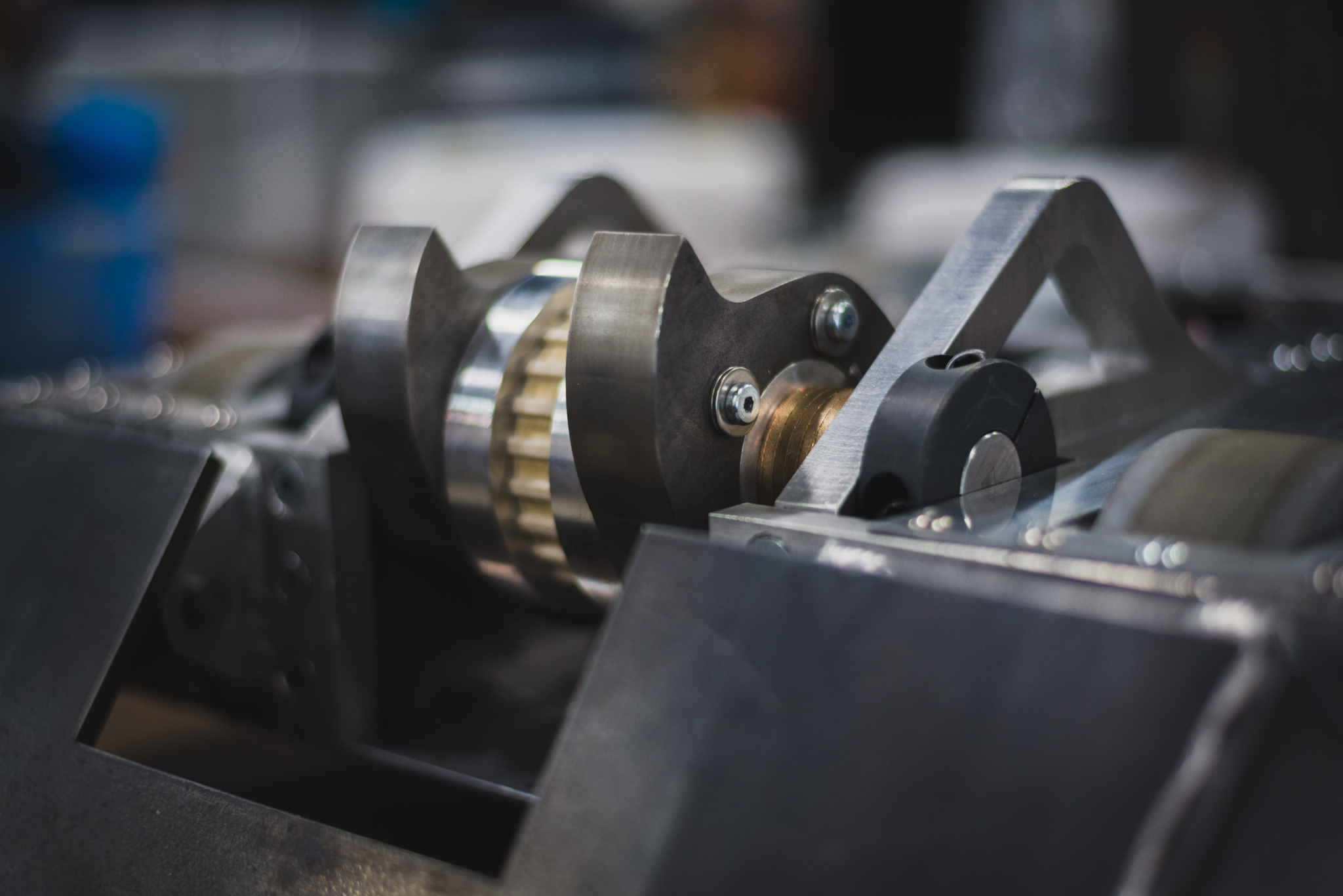
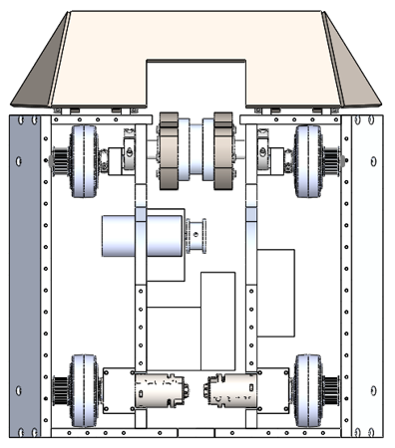
Wedgie’s weapon system consists of a dual vertical spinner and a front wedge. With the front wedge ground flat, opponents are pushed up onto the wedge and then hit by the vertical spinner, which flips them or inflicts damage underneath.
The vertical spinner comprises of two thick steel “blades” mounted on a center pulley driven by a nylon-Kevlar belt. The pulley contains a press-fitted lubricated bushing that allows it to rotate about a fixed steel shaft. Oil-impregnated washers prevent the screws fastening the blades from colliding with the middle members when spinning erratically.
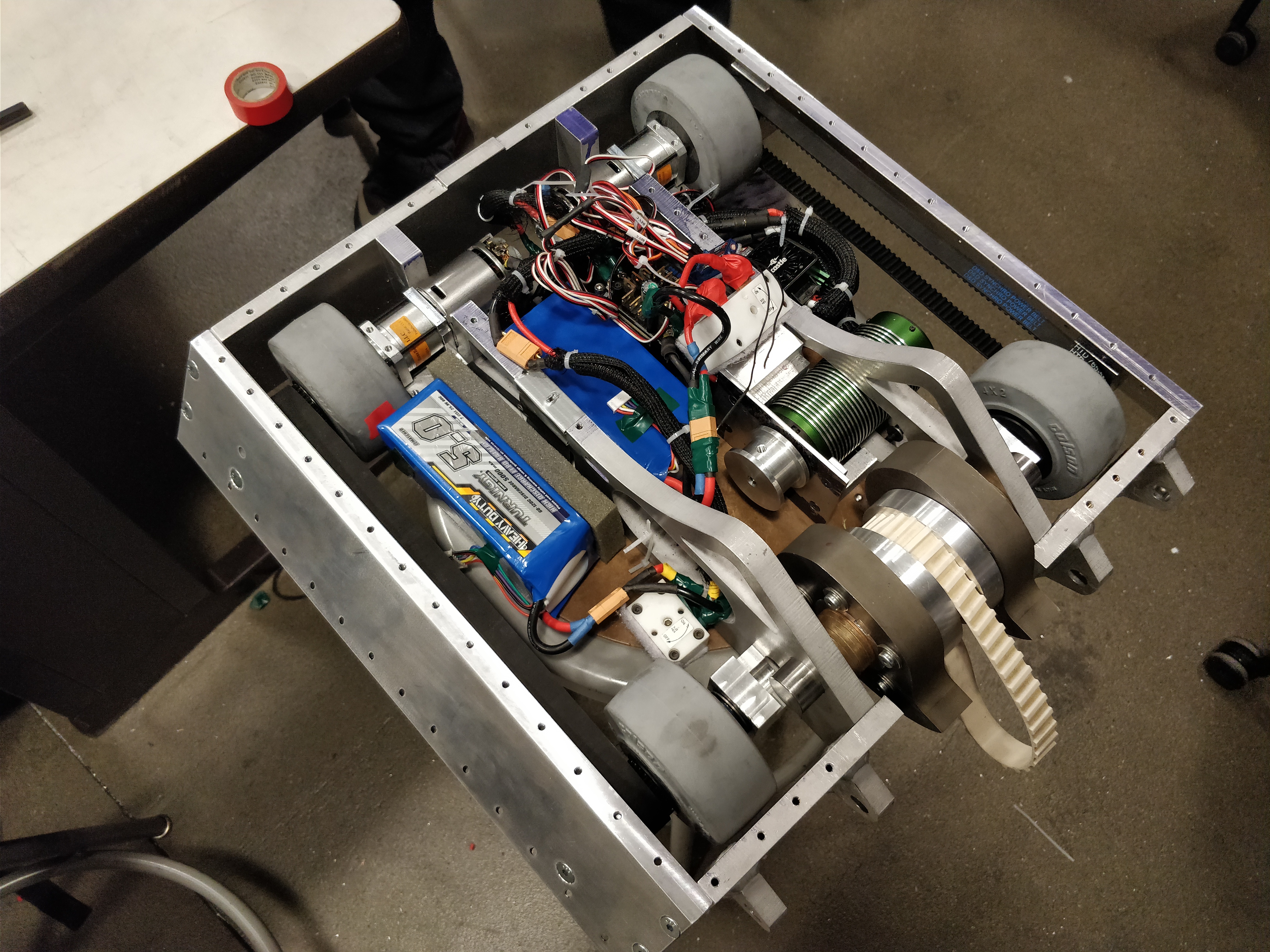
Electronics System
Wedgie’s four wheel drive was propelled by Dewalt 18V drill motors, each connected to an old motor controller after our Ragebridge 2 accidentally shorted. The weapon itself was powered by a Mamba XLX Extreme 800kV brushless motor. Both the drive and weapon system were linked together and fueled by a LiPo battery. The entire robot was remote controlled.
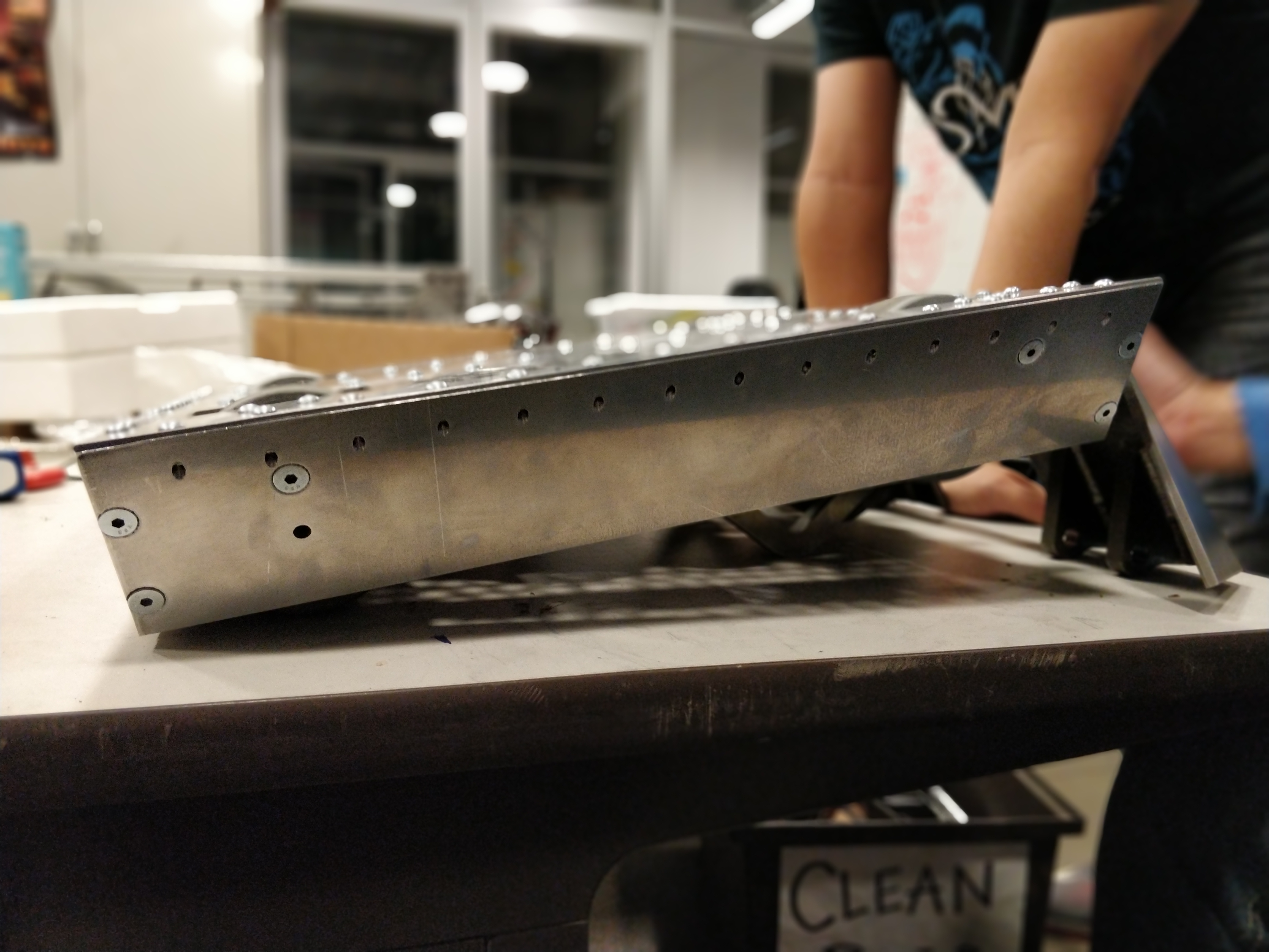
Materials Selection and Manufacturing
The metal blades were 1” thick AR400 steel sheets cut on a wire EDM, while the wedge was a ¼” thick 4140 steel sheet welded together after sectioned off with a wire EDM. The front wall with tabs connecting the wedge were made of 6013 for its weldability and durability. The remaining walls were made of waterjetted 7075 aluminum. Each of these waterjetted parts had holes drilled into the edges for mounting the top and bottom plates. The side walls and wheel mounts, being at an angle, required the use of an angle vise in order to mill bevels on the side walls and angled faces on the outermost wheel mounts.
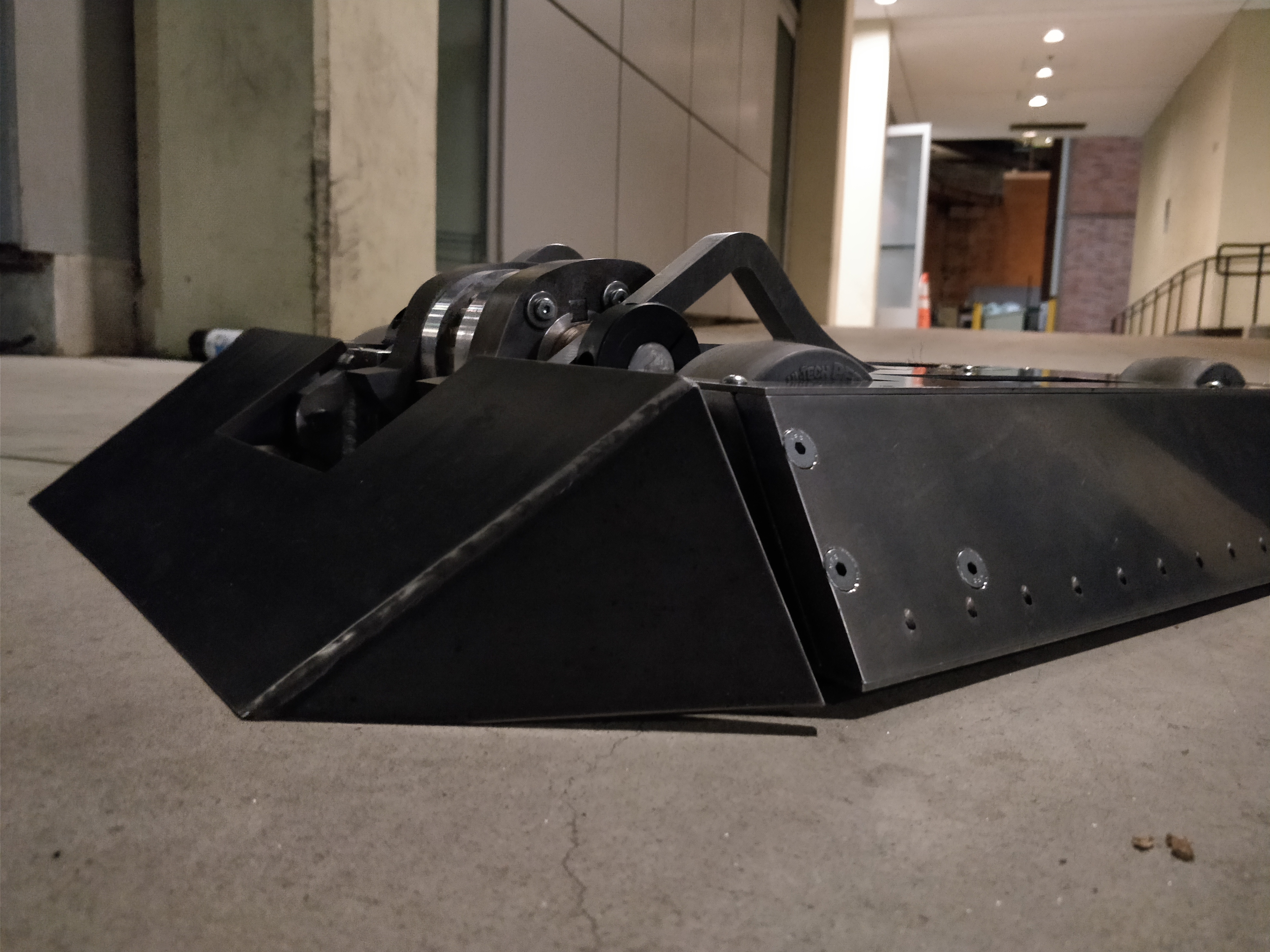
Invertible Frame
Wedgie’s frame was designed such that it guided any external loads through the frame and could still move via the rear wheels when flipped over.